How to Cool High-Power IGBT Modules
High-power IGBT modules are widely used in industrial inverters, photovoltaic systems, motor drives, UPS equipment, welding machines and electric vehicle power electronics. Although IGBTs are designed to handle high voltage and current, part of the electrical energy is inevitably converted into heat during conduction and switching. If this heat cannot be transferred away efficiently, the junction temperature will continue to rise, affecting efficiency, service life and operating reliability.
For this reason, high-power IGBT module cooling should be considered as part of the complete electrical and mechanical design. A suitable heat sink or liquid cold plate is important, but it is only one part of the overall thermal path. The module structure, thermal interface material, mounting method, airflow or coolant flow and operating environment must all work together.
Why High-Power IGBT Modules Generate Heat
The heat generated by an IGBT module mainly comes from conduction losses and switching losses. When the IGBT is turned on, a voltage drop remains between the collector and emitter. Under high current, this voltage drop produces continuous conduction loss. The approximate conduction loss can be evaluated from the collector-emitter saturation voltage, collector current and duty cycle.
Switching losses occur when the device turns on and off. During these short transition periods, voltage and current overlap inside the device, creating additional power dissipation. As switching frequency increases, switching losses generally become more significant. This means that two inverter systems using the same IGBT module may require completely different cooling designs if their load current, switching frequency or operating cycles are different.
The total thermal load should therefore be calculated under actual operating conditions rather than estimated only from the module’s nominal current rating. Continuous load, peak load, ambient temperature, modulation method, switching frequency and overload duration can all influence the final heat dissipation requirement.
Understanding the IGBT Thermal Path
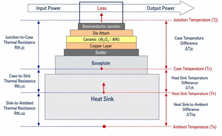
Heat begins at the semiconductor junction and travels through the internal structure of the module before reaching the surrounding environment. It normally passes through the chip solder layer, substrate, baseplate and thermal interface material before entering the heat sink or cold plate. From there, the heat is transferred to air or coolant.
Every layer along this path has a certain thermal resistance. The combined resistance determines how easily heat can move away from the junction. If one layer has excessive resistance, improving another part of the system may provide limited benefit.
The junction temperature can be estimated by adding the product of power loss and total thermal resistance to the ambient temperature. In a conventional air-cooled design, the calculation normally includes junction-to-case resistance, case-to-sink resistance and sink-to-ambient resistance. This calculation allows engineers to determine whether the selected heat sink can maintain the IGBT junction temperature below its maximum permitted value.
It is important to leave a reasonable design margin. A cooling system that performs adequately at room temperature may become insufficient when the inverter operates in a hot enclosure, under overload or in a location with restricted airflow.
Air Cooling for IGBT Modules
Air-cooled heat sinks remain a practical solution for many industrial power electronics systems. They are relatively simple to install, easy to inspect and suitable for applications where the heat load and power density are within a manageable range.
The performance of an air-cooled heat sink depends on more than its external dimensions. The baseplate must provide a sufficiently flat and stable contact surface for the IGBT module. The fin structure must allow air to pass through without excessive pressure drop. The fan must provide suitable airflow at the actual system resistance, not only under free-air conditions.
Airflow distribution is also important. If one section of the heat sink receives less airflow than another, the module may develop local hot spots even when the average heat sink temperature appears acceptable. The heat sink orientation, fan position, enclosure design and surrounding components should therefore be considered during thermal validation.
Natural convection may be sufficient for lower-power systems, but it becomes difficult to use when the heat load is high or the enclosure is compact. Forced-air cooling can significantly reduce thermal resistance, although the reliability of the fan must then be included in the system design.
Liquid Cooling for High Power Density
Liquid cooling is often selected when air cooling cannot provide sufficient thermal performance within the available space. A liquid cold plate transfers heat from the IGBT module into a coolant flowing through internal channels. Because liquids can carry substantially more heat than air within a compact volume, liquid cooling is suitable for high-power inverters and other applications with strict space or temperature requirements.
A well-designed liquid cold plate can reduce thermal resistance, improve temperature uniformity and provide a more compact installation than a large finned heat sink. The internal channel structure must be designed according to the heat distribution of the IGBT module. Areas beneath the hottest devices should receive sufficient cooling capacity, while the channel layout should avoid unnecessary pressure loss.
The cooling design must also consider coolant compatibility, sealing reliability, corrosion resistance and long-term thermal cycling. The inlet and outlet arrangement should support stable flow through the entire cold plate. If the coolant flow is uneven or partially restricted, certain areas of the module may operate at a considerably higher temperature than expected.
For demanding applications, the cold plate should be evaluated not only through thermal simulation but also through flow testing, pressure testing and long-duration reliability testing.
The Importance of Thermal Interface Materials
The contact layer between the IGBT module and the heat sink or cold plate can have a major influence on total thermal resistance. Even when the cooling component has excellent performance, poor contact quality can prevent heat from leaving the module efficiently.
Thermal grease, phase-change materials, thermal pads and electrically insulating interface materials are commonly used in IGBT assemblies. The most suitable option depends on the required electrical insulation, surface condition, mounting pressure, operating temperature and expected service life.
The thickness of the interface layer should be controlled carefully. A layer that is too thick may increase thermal resistance, while insufficient material may leave air gaps between the two surfaces. The contact surfaces should also be clean and sufficiently flat before assembly.
Mounting pressure must be distributed evenly across the module baseplate. Excessive pressure can deform the package, while insufficient pressure may cause poor contact and localized overheating. For this reason, the recommended screw pattern, tightening sequence and torque should be followed during assembly.
Mechanical Design and Thermal Reliability
The mechanical structure of an IGBT cooling system affects its thermal performance throughout the product life cycle. The heat sink or cold plate must remain securely connected to the module despite vibration, thermal expansion and repeated power cycling.
Different materials expand at different rates as temperature changes. If the module baseplate, interface material and cooling component expand unevenly, mechanical stress may accumulate in the assembly. Over time, this can affect contact quality, solder joints and package reliability.
A reliable thermal design should therefore be evaluated under actual operating conditions. Testing should include maximum continuous load, high ambient temperature, peak current, repeated start-stop cycles and power cycling. For liquid-cooled systems, coolant leakage, pressure resistance and flow stability must also be verified.
Temperature measurements should be taken at representative locations, including the module case, heat sink or cold plate surface, coolant inlet and coolant outlet. These measurements can reveal whether the system is operating uniformly or whether a local hot spot is developing.
How to Select the Right IGBT Cooling Solution
The selection between air cooling and liquid cooling should be based on the actual heat load, installation space, ambient temperature, operating profile and reliability requirements. Air cooling may be suitable when the power density is moderate and sufficient space is available for a heat sink and fan. Liquid cooling becomes more attractive when the inverter is compact, the heat flux is high or the junction temperature must be controlled more tightly.
The cooling component should be designed around the complete application rather than selected only from a standard size chart. The IGBT module dimensions, mounting holes, heat distribution, electrical insulation requirements, coolant conditions and production volume all influence the final design.
Ecothermgroup develops thermal management solutions for power electronics applications, including custom heat sinks, liquid cold plates and inverter cooling components. Customers can provide the module drawing, power loss, operating temperature range, installation dimensions and coolant requirements so that the thermal path can be evaluated before production.
Frequently Asked Questions
What is the most effective way to cool a high-power IGBT module?
The most effective method depends on the total heat load and power density. Air-cooled heat sinks are suitable for many industrial systems, while liquid cold plates are generally more effective when the available space is limited or the heat flux is high.
Why can an IGBT module overheat even when a large heat sink is installed?
Overheating may be caused by insufficient airflow, poor contact between the module and heat sink, excessive thermal interface material, incorrect mounting pressure or underestimated switching losses. A large heat sink cannot compensate for a poorly designed thermal path.
Does thermal grease improve IGBT cooling performance?
Thermal grease can reduce contact resistance when it is applied as a thin and uniform layer between properly prepared surfaces. Excessive application, uneven spreading or long-term pump-out can reduce its effectiveness.
When should liquid cooling be considered?
Liquid cooling should be considered when air cooling cannot maintain the required junction temperature, when the inverter enclosure is compact or when the application requires high heat removal capacity and consistent temperature distribution.
What information is needed to design a custom IGBT cooling system?
A thermal design review normally requires the IGBT module drawing, estimated conduction and switching losses, operating current, switching frequency, ambient temperature, installation space, mounting requirements and, for liquid cooling, the coolant type, flow rate and allowable pressure drop.
Request a Custom IGBT Cooling Solution
Send Ecothermgroup your IGBT module drawings, heat-load data, operating conditions and installation requirements. Our engineering team can evaluate the thermal path and recommend a suitable air-cooled heat sink, liquid cold plate or custom inverter cooling solution.