AI Server Rack Cold Plate: GPU Heat Removal, Materials & Design Data
AI server rack cold plates are used when air cooling cannot control GPU and CPU heat density. A well-designed cold plate moves heat from the chip into coolant, while controlling pressure drop, leakage risk, material compatibility, and rack-level serviceability.

What Is an AI Server Rack Cold Plate?
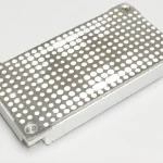
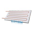
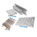
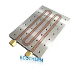
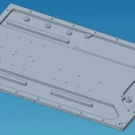
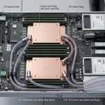
An AI server rack cold plate is a liquid-cooled metal plate mounted on high-power chips such as GPUs, CPUs, ASICs, switch chips, or power modules. Coolant flows through internal channels and carries heat away from the server.
In AI racks, the cold plate is not only a thermal part. It is also a fluid, mechanical, sealing, and reliability component. A poor design may cool well in a lab test but fail in rack deployment because of excessive pressure drop, leakage risk, poor flatness, or coolant compatibility issues.
| Item | Typical design point | Why it matters |
|---|---|---|
| Cooling target | GPU, CPU, ASIC, switch chip | AI workloads create dense heat sources |
| Cooling method | Direct-to-chip liquid cooling | Shorter thermal path than air cooling |
| Common materials | Copper, aluminum, stainless steel | Affects conductivity, weight, cost, and corrosion |
| Internal structure | Channels, microchannels, skived fins, manifold flow | Controls heat transfer and pressure drop |
| Connection | Tubes, manifolds, quick connectors, CDU | Determines rack integration and maintenance |
| Key tests | Leak, pressure drop, flow, flatness, thermal test | Controls deployment reliability |
AI Server Cold Plate: How Does It Remove Heat from GPUs and CPUs?
An AI server cold plate removes heat by placing liquid flow close to the heat source. Heat travels from the chip package into the cold plate base, then into coolant through the internal channel surface.
The basic heat path is:
GPU / CPU → TIM → cold plate base → internal channels → coolant → CDU / heat exchanger| Heat transfer stage | What happens | Data to check |
|---|---|---|
| Chip to TIM | Heat leaves the chip package | TIM type, thickness, contact pressure |
| TIM to cold plate | Heat enters the metal base | Flatness, material, base thickness |
| Cold plate to coolant | Heat transfers into liquid | Channel geometry, flow rate, wetted area |
| Coolant to CDU | Heat leaves the server | Pressure drop, connector loss, coolant temperature |
| CDU to facility loop | Heat is rejected outside the rack | Heat exchanger capacity and water temperature |
Practical rule: the target is not just lower temperature. The target is lower thermal resistance at a pressure drop the rack cooling loop can support.
GPU Cold Plate Heat Removal: What Internal Structure Matters?
GPU cold plate heat removal depends on how much internal surface area contacts the coolant and how evenly coolant reaches the hotspot area.
For high-power GPU modules, simple straight channels may not be enough. Designs often use parallel channels, split-flow structures, microchannels, or internal skived fins to increase the wetted surface area above the heat source.
| Internal structure | Thermal effect | Limitation |
|---|---|---|
| Straight channels | Simple and robust | Lower surface area |
| Parallel channels | Lower flow resistance | Flow distribution must be controlled |
| Microchannels | Higher heat transfer area | Higher pressure drop and clogging risk |
| Internal skived fins | High surface area near hotspot | More process control required |
| Split-flow design | Sends cooler fluid to hotspot first | More complex manifold design |
| Jet impingement | Strong local cooling | Higher pressure drop and complexity |
Practical rule: smaller channels and denser fins can improve heat transfer, but they also increase pressure drop. The design must balance both.
Monolithic Cold Plates for AI vs O-Ring Sealed Cold Plates
Monolithic cold plates for AI are designed to reduce joints and sealing interfaces. They can be made by processes such as vacuum brazing, friction stir welding, diffusion bonding, or precision CNC structures depending on material and channel design.
O-ring sealed cold plates are easier to assemble and inspect, but elastomer seals can become a risk under long-term thermal cycling, pressure cycling, and service conditions.
| Factor | O-ring sealed cold plate | Monolithic / welded / brazed cold plate |
|---|---|---|
| Sealing method | Rubber seal + screws | Metal-to-metal joining or integrated structure |
| Leakage risk | Depends on seal aging and assembly quality | Lower seal-interface risk |
| Maintenance | Easier to disassemble | Usually not designed for disassembly |
| Pressure capability | Depends on O-ring and screws | Often stronger when process is well controlled |
| Internal channel flexibility | Good | Depends on joining process |
| Best use | Low-to-medium pressure, serviceable designs | High-reliability AI server cold plates |
Practical rule: monolithic designs are worth evaluating when leakage control, compact structure, and long-term reliability are more important than easy disassembly.
Server CPU Cold Plate Solution: Copper, Aluminum or Stainless Steel?
A server CPU cold plate solution can use copper, aluminum, stainless steel, or coated metal depending on heat load, coolant chemistry, weight, cost, and corrosion requirements.
Copper is usually selected for high heat flux areas because it has much higher thermal conductivity. Aluminum can reduce weight and cost but needs careful coolant compatibility. Stainless steel has much lower conductivity and is usually used only for special fluid or corrosion conditions.
| Material | Typical thermal conductivity | Weight | Cost | Best use |
|---|---|---|---|---|
| Copper | ~390–400 W/m·K | Heavy | Higher | GPU cold plates, high heat flux CPUs, compact hotspots |
| Aluminum | ~160–205 W/m·K | Light | Lower | Larger plates, cost-sensitive systems, aluminum loops |
| Stainless steel | ~15–20 W/m·K | Medium | Medium | Corrosion-focused or special fluid environments |
| Coated copper | High | Heavy | Higher | High performance with corrosion control |
| Coated aluminum | Medium | Light | Lower | Lightweight server cooling with compatible coolant |
Practical rule: choose copper for thermal performance near dense chips. Choose aluminum when weight, cost, and system material compatibility are more important.
Server Cold Plate for High Heat Flux CPUs: What Data Should Engineers Check?
For a server cold plate for high heat flux CPUs, total power is not enough. The same 500 W can be easy or difficult depending on heat source area, hotspot map, coolant flow, and maximum temperature limit.
Engineers should compare cold plates using the same test conditions. A thermal resistance number without flow rate, inlet temperature, and heat source size is not useful.
| Data point | Why it matters | Example |
|---|---|---|
| Chip power / TDP | Defines total heat load | 300 W, 500 W, 1000 W-class module |
| Heat source size | Defines heat flux | 35 × 35 mm package |
| Hotspot map | Guides channel placement | Center or edge hotspot |
| Coolant inlet temperature | Defines thermal headroom | 25°C, 35°C, 45°C |
| Flow rate | Affects heat transfer | L/min per cold plate |
| Pressure drop | Affects pump and CDU design | kPa at rated flow |
| Maximum temperature | Sets design target | Case, junction, or surface limit |
| Mounting pressure | Controls TIM resistance | Screw torque or spring load |
Practical rule: compare thermal resistance and pressure drop together. A cold plate that cools well but creates too much pressure drop may not be suitable for rack deployment.
Custom Cold Plate for Cloud Computing Hardware: What Should Be Customized?
A custom cold plate for cloud computing hardware should be designed around the full server layout, not only the GPU or CPU package.
Cloud and AI hardware require repeatability, serviceability, low leakage risk, clean internal channels, stable connectors, and predictable pressure drop across many servers.
| Custom item | What to define | Why it matters |
|---|---|---|
| Contact area | Chip size, package outline, keep-out zones | Prevents poor contact and local overheating |
| Channel layout | Serpentine, parallel, microchannel, split-flow | Balances heat transfer and pressure drop |
| Inlet / outlet | Connector location and tube routing | Affects assembly and maintenance |
| Mounting holes | Screw locations and pressure limits | Protects chip package and TIM contact |
| Material | Copper, aluminum, coating | Affects performance and corrosion |
| Surface flatness | Contact surface tolerance | Reduces interface resistance |
| Leak test | Pressure and holding time | Controls field failure risk |
| Cleanliness | Particle and residue control | Protects pumps, valves, and microchannels |
Practical rule: for cloud hardware, a cold plate is part of the rack cooling architecture. It must match the server layout, coolant loop, CDU, manifold, and maintenance method.
Server Cold Plate Technology: Flow Path, Pressure Drop and Reliability
Server cold plate technology is mainly about balancing heat transfer, flow resistance, manufacturability, and reliability.
A more aggressive flow path may reduce chip temperature, but it can also increase pressure drop. A low-pressure design may be easier for the pump, but it may not cool the hotspot enough.
| Design factor | Improves | May increase |
|---|---|---|
| Higher flow rate | Heat transfer | Pump power and pressure drop |
| Smaller channels | Heat transfer area | Clogging risk and pressure drop |
| More turbulence | Heat transfer coefficient | Flow resistance |
| Thinner base | Lower conduction path | Mechanical deformation risk |
| Better flatness | Lower TIM resistance | Machining cost |
| Larger connector | Flow capacity | Space and serviceability limits |
| Higher leak test pressure | Reliability confidence | Process time |
Common reliability checks
| Test item | Purpose |
|---|---|
| Leak test | Check sealing and pressure integrity |
| Pressure drop test | Verify flow resistance |
| Flow distribution test | Confirm each channel receives coolant |
| Flatness inspection | Ensure chip contact quality |
| Dimensional inspection | Confirm mounting and connector fit |
| Thermal test | Verify performance under load |
| Corrosion compatibility review | Reduce long-term coolant loop risk |
| Cleanliness control | Prevent particles entering the loop |
How to Request a Custom AI Server Cold Plate Quote
For a custom AI server cold plate, send both thermal data and mechanical constraints. A drawing alone is not enough if the supplier does not know flow rate, coolant, pressure drop limit, or chip power map.
| Required data | Example |
|---|---|
| Chip type | GPU, CPU, ASIC, switch chip |
| Heat load | 500 W, 800 W, 1000 W-class module |
| Heat source size | Package size and hotspot map |
| Maximum temperature | Case or junction temperature target |
| Coolant type | DI water, water-glycol, dielectric coolant |
| Inlet temperature | 25°C, 35°C, 45°C |
| Flow rate target | L/min per cold plate |
| Pressure drop limit | kPa or bar at target flow |
| Mounting layout | Screw holes, spring load, keep-out zone |
| Plate size limit | Length, width, height |
| Material preference | Copper, aluminum, coated metal |
| Quantity | Prototype, pilot run, production |
Practical rule: if the project is still in the design stage, send the chip power, available space, coolant condition, and target flow. A supplier can then recommend channel type, material, joining process, and test plan.
FAQ
An AI server rack cold plate is a liquid-cooled metal plate mounted on GPUs, CPUs, or other hot chips. It transfers heat into coolant for high-density server cooling.
Cold plates are used because AI GPUs and CPUs produce high heat density. Direct-to-chip liquid cooling removes heat more efficiently than air cooling in dense racks.
A GPU cold plate often needs a larger custom layout and hotspot-focused channel design. A CPU cold plate is usually more socket-based and standardized.
They can reduce seal-interface risk and improve structural reliability. However, they may increase machining or joining cost, so the choice depends on channel design and volume.
Use parallel flow paths, optimized channel width, split-flow layouts, and smooth inlet/outlet transitions. The goal is enough heat transfer without overloading the pump or CDU.
Send chip power, heat source size, maximum temperature, coolant type, inlet temperature, flow rate, pressure drop limit, mounting layout, available space, material preference, and quantity.