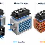
Analysis of Heat Pipe Cooling Technology, Working Principle
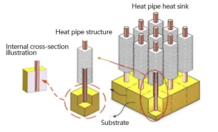
How Gravity Orientation Impacts Heat Pipe Qmax (Maximum Heat Transfer)
While the internal sintered powder wick provides excellent capillary pumping force to return the working fluid, gravity still plays a critical role in real-world thermal design. A common mistake in product design is assuming a heat pipe will perform equally in all orientations.
Gravity-Assisted (Evaporator at bottom):
This is the optimal orientation. The Qmax reaches 100% efficiency as gravity aids the capillary action in returning the condensed liquid.
Horizontal Orientation:
Performance typically drops to approximately 70-80% of the maximum theoretical Qmax.
Against Gravity (Evaporator at top): This is the worst-case scenario. The capillary wick must fight gravity, and performance (Qmax) can severely degrade by 50% or more, depending on the heat pipe length and wick thickness.
When designing for against-gravity applications, engineers must specify a thicker sintered wick or opt for Vapor Chamber solutions to prevent premature dry-out at the evaporator end.
| Pipe type / diameter | Orientation (best / horizontal / worst) | Typical Qmax (W) | Design note |
| Copper sintered Ø5 mm | Bottom / Horizontal / Top | 80 / 50–60 / 30–40 | Small form factor, sensitive to length |
| Copper grooved Ø8 mm | Bottom / Horizontal / Top | 250 / 200 / 120–160 | Good for moderate lengths |
| Vapor chamber (flat) | N/A | 200–1000+ (area dependent) | Use for uniform spread across die |
Heat Pipe Internal Heat Transfer: Key Mechanisms and Advantages
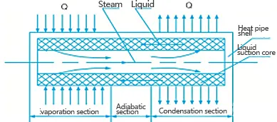
High Thermal Conductivity via Vapor-Liquid Phase Change
Excellent Isothermal Performance
- The vapor inside the heat pipe remains in a saturated state, where vapor pressure is directly tied to temperature.
- Minimal pressure drop occurs as saturated vapor flows from the evaporation section to the condensation section.
- Thermodynamic principles ensure minimal temperature variation (ΔT ≤ 1-2°C), granting the heat pipe near-isothermal characteristics.
Key engineering parameters (quick reference for designers)
1.Common working fluids and approximate operating ranges:
- Water — widely used for electronic cooling; practical operating range roughly 0°C to ~270°C (long‑term reliability upper bound ≈ 270°C).
- Methanol/ethanol — for low‑temperature applications where water is unsuitable.
- Ammonia and liquid metals (Na, K, Li) — used for low‑temperature or very high‑temperature applications respectively.
2.Typical performance metrics (engineering guidance)
- Effective thermal conductivity: in the operating regime a heat pipe often behaves like a solid conductor with an apparent conductivity of several thousand to ten‑thousand W/(m·K).
- Power capacity: a single small‑diameter heat pipe typically carries from a few watts up to several tens of watts in common consumer/industrial configurations; customised designs, multiple parallel pipes, vapor chambers or pulsating heat pipes are used where heat transport requirements reach hundreds to thousands of watts. Exact capacity depends on diameter, wick geometry and cold‑end heat‑sink performance.
3.Design limits to consider early in development
- Capillary limit: when the wick cannot return sufficient condensate to the evaporator, dry‑out occurs — this limit scales with wick permeability, geometry and pipe dimensions.
- Boiling/heat‑flux limit: excessive local heat flux at the evaporator can trigger film boiling and reduce heat transfer effectiveness.
- Non‑condensable gas contamination and leakage: retained gases or seal degradation reduce performance and can produce localized hot spots; manufacturing cleanliness and leak integrity are critical.
| Parameter | Typical range / example | Notes |
| Working fluid | Water / Methanol / Ammonia / Liquid metals | Temperature range and typical use cases |
| Effective thermal conductivity | 3,000–15,000 W/(m·K) (apparent) | Depends on vapor path & geometry |
| Typical Qmax (per pipe) | Ø4–6 mm: 20–80 W Ø8–12 mm: 80–300 W | Orientation sensitive |
| Typical Rth (example) | 0.05–0.5 °C/W | Measured at specified boundary conditions; dependent on interface & fin |
| Max operating temp | Water up to ~270°C; liquid metals higher | Long‑term reliability limits |
Adjustable Heat Flux Density
Reversible Heat Flow Direction
Thermal Diode and Switch Functions
- Thermal Diode: Permits unidirectional heat flow while blocking reverse conduction, ideal for thermal isolation in specialized systems.
- Thermal Switch: Activates heat transfer when the heat source temperature exceeds a threshold and ceases operation below it, enabling precise thermal control.
Constant Temperature Regulation
- Traditional heat pipes have fixed thermal resistance, causing temperature fluctuations with varying heat loads.
- Variable-conductance heat pipes adjust the condensation section’s thermal resistance dynamically: reducing it with increased heat input and increasing it with decreased input. This maintains minimal steam temperature variation (±0.5°C) across large heat load changes.
Strong Environmental Adaptability
- Customizable Shapes: Molded into diverse forms (e.g., motor shafts, turbine blades, surgical tools) or split designs for long-distance heat transfer without fluid mixing.
- Gravity-Insensitive Operation: Functions effectively in both terrestrial (gravitational) and space (zero-gravity) environments.
Selection and design guidance
Start with three inputs: peak heat load (W), allowable maximum temperature (°C), and orientation/space constraints. These three items are sufficient to generate initial candidate diameters, wick types and whether a vapor chamber or liquid‑cooled approach is more appropriate.
Rules of thumb:
- Low to moderate point loads (< ~100 W) with limited volume: standard round heat pipes with sintered or grooved wicks are often the most cost‑effective solution.
- Applications requiring a thin, uniform thermal spread over an area: consider a vapor chamber for lower thermal resistance and a thinner profile.
- High concentrated heat or multi‑kW scenarios: evaluate liquid cooling or hybrid approaches (vapor chamber + liquid cold plate, or pulsating heat pipes) rather than relying on single heat pipes.
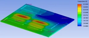
- Deliverables to request from your supplier: steady‑state thermal resistance estimate (°C/W), recommended pipe diameter and wick type, mounting and attachment recommendations, and if possible a simple thermal model or CFD snapshot for validation.
| Technology | Best for | Typical power range | Profile / Mass | Cost (relative) | Orientation sensitivity |
| Heat pipe | Point-to-point transfer | Tens–few hundreds W | Low profile, light | Low–medium | Low (wicked) to high (gravity only) |
| Vapor chamber | Uniform spread, thin devices | 50–1000 W (area dependent) | Very low profile, moderate mass | Medium–high | Low |
| Liquid cold plate | High heat flux, kW range | Hundreds–kW | Higher mass, plumbing required | High | Low (pump required) |
| Pulsating heat pipe (PHP) | Compact, moderate power | Tens–few hundreds W | Compact, variable mass | Medium | Moderate |
| Required input from buyer | Example value | Why needed |
| Peak power (W) | 250 W | Determines candidate Qmax and margin |
| Allowable Tmax (°C) | 85 °C | Sets thermal resistance target |
| Mounting envelope (L×W×H) | 120×40×10 mm | Mechanical integration and pipe routing |
| Orientation in service | Rotating / upright / any | Affects wick choice and margin |
| Target quantity & lead time | 1000 pcs / 8 weeks | Affects manufacturing method and costing |
Disadvantages of Heat Pipe Technology
Higher Production Costs
Complex Installation and Maintenance
- Requires technical expertise for proper installation, ensuring optimal contact between heat pipes, heat sources, and cooling fins to maximize heat transfer efficiency.
- Regular maintenance (e.g., dust cleaning, leakage inspections) adds operational complexity and cost.
Environmental Sensitivity
Leakage Risks
Size and Shape Limitations
Uneven Heat Distribution
Troubleshooting and installation best practices
Thermal contact:
for reliable low contact resistance use soldered or brazed copper interfaces where possible. Thin thermal pads or adhesives increase contact resistance and should be validated in prototype testing.
Orientation and wick selection:
modern wicked heat pipes (sintered, mesh, grooved) maintain capillary return in multiple orientations; gravity‑assisted designs without a wick are more sensitive to orientation and should be used only when installation is well controlled.
Dry‑out and contamination diagnosis:
indicators of dry‑out include persistent local temperature rise at the evaporator and non‑uniform temperature distribution along the pipe. Diagnose by checking contact resistance, cold‑end sink capacity and then manufacturing records for vacuum and charge quality.
Attachment and reliability:
for products requiring high reliability use metallurgical joints (brazing/soldering). Adhesive or tape attachment can be acceptable for consumer products but must be validated with thermal cycling, moisture and vibration testing.
Applications of Heat Pipe Technology
Electronics Cooling
- CPU and GPU Cooling: Critically dissipates heat from high-performance computing devices (e.g., gaming laptops) to prevent overheating, performance throttling, and hardware damage.
- Smartphone Cooling: Embedded heat pipes in premium smartphones transfer processor heat to the casing, enhancing user experience and battery longevity.
- Peripheral Cooling: Manages heat in hard drives, RAM, and power modules for stable system operation.
Aerospace Engineering
- Satellite Thermal Control: Efficiently transfers internal heat to radiators, stabilizing temperatures during extreme space conditions (e.g., solar exposure and Earth shadow cycles).
- Spacecraft Thermal Protection: Mitigates aerodynamic heating during re-entry by conducting heat away from critical structures and components.
Renewable Energy
- Solar Water Heaters: Rapidly transfers solar collector heat to storage tanks, minimizing losses and enhancing efficiency across weather conditions.
- Wind Turbines: Cools generators and electronics while enabling blade de-icing via heat transfer, improving reliability in harsh environments.
Industrial Applications
- Waste Heat Recovery: Captures and repurposes industrial waste heat for preheating processes (e.g., steel and cement production), reducing energy costs and carbon footprint.
- Chemical Processing: Maintains precise reaction temperatures in high-pressure/high-temperature environments, enhancing product quality and operational safety.
- Machinery Cooling: Cools cutting tools and spindles in CNC machines, reducing wear, thermal deformation, and improving machining precision.
Other Sectors
- Medical Equipment: Stabilizes temperatures in MRI machines and laser devices to ensure diagnostic/therapeutic accuracy and equipment reliability.
- LED Lighting: Efficiently dissipates LED chip heat, slowing lumen depreciation and extending lifespan in commercial and residential lighting applications.
FAQ
How much power can a single heat pipe carry?
Capacity depends on diameter, wick structure and the cold‑end heat‑sink. Typical small‑diameter pipes carry from a few watts to low hundreds of watts under good boundary conditions. For higher power, use multiple pipes, vapor chambers or liquid cooling; provide your thermal load and boundary conditions for an accurate recommendation.
When should I choose a vapor chamber instead of heat pipes?
Choose a vapor chamber when you need a low‑profile, uniform thermal spread across a surface (e.g. thin electronics, high‑power die). Use heat pipes when the primary requirement is to move heat between separated locations and space allows for pipe routing.
Are heat pipes maintenance‑free and leak‑proof?
Heat pipes are sealed and contain no moving parts, so they require no routine maintenance. However, their performance depends on long‑term seal and wick integrity; critical applications should include leak and accelerated aging tests.
Is heat‑pipe performance sensitive to installation orientation?
Wicked heat pipes are designed to operate in any orientation. Gravity‑assisted designs without capillary return show better performance when installed vertically with the evaporator below the condenser.
What are the signs of heat‑pipe failure and how do I test for them?
Typical signs are a persistent hot spot at the evaporator, higher than expected thermal resistance, or a non‑uniform temperature profile. Useful tests include multi‑point thermocouple mapping under steady load, transient power step tests, and inspection of manufacturing vacuum/charge records.
Do you provide CAD and test data for evaluation?
Yes. We can supply STEP/CAD samples and abbreviated test reports for initial evaluation; full test datasets are available on request or as part of a development engagement. Submit your thermal load and mechanical constraints to receive files and a preliminary feasibility assessment.