How to Cool a High-Power IGBT Module
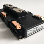
Cooling a high-power IGBT module requires more than attaching the module to a large heat sink. The real engineering task is to create a continuous, low-resistance thermal path from the semiconductor junction to the surrounding air or coolant. That path includes the internal module package, the module baseplate, the contact interface, the heat sink or liquid cold plate, and the final cooling medium. If any one of these sections performs poorly, the junction temperature can remain high even when the external cooling component appears adequately sized.
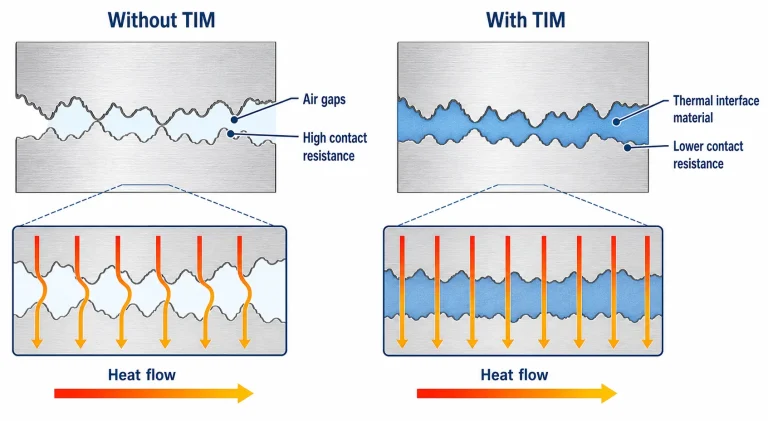
For most baseplate-mounted IGBT modules, the interface between the module and the cooling component deserves particular attention. Two metal surfaces that look smooth to the eye touch only at microscopic high points. The remaining spaces contain air, which conducts heat poorly. A thermal interface material fills these voids and lowers contact resistance, but it must be selected and applied correctly. Too little material leaves unfilled gaps, while an unnecessarily thick layer creates an additional barrier to heat flow.
Where Does the Heat in an IGBT Module Come From?
An IGBT module produces heat mainly through conduction losses and switching losses. Conduction loss develops while current flows through the IGBT and its companion diode. Switching loss occurs during turn-on and turn-off, when voltage and current overlap for a brief period. The total dissipation depends on load current, DC-link voltage, switching frequency, modulation strategy, gate resistance, cooling conditions and junction temperature.
This relationship is important because power loss and temperature influence each other. A higher junction temperature can change the electrical characteristics of the semiconductor, which can increase loss under some operating conditions. The thermal design should therefore be based on losses calculated or measured at realistic temperatures rather than on a room-temperature estimate alone.
The required cooling capacity also depends on the load profile. A motor drive may experience short acceleration peaks, while a solar inverter may operate near continuous high load for several hours. The first case requires careful transient thermal analysis; the second places greater emphasis on steady-state thermal resistance. Both must keep the junction temperature within an appropriate operating margin below the module’s absolute maximum rating.
How Heat Travels from the Junction to the Environment
Inside the module, heat flows from the semiconductor die through the die-attach layer, metallized ceramic substrate and baseplate. It then crosses the interface between the module and the heat sink or liquid cold plate. Finally, the cooling component transfers the heat to air or coolant.
The total steady-state thermal resistance can be expressed as the sum of junction-to-case resistance, case-to-sink resistance and sink-to-ambient resistance. In simplified form, this is written as Rth,j-a = Rth,j-c + Rth,c-s + Rth,s-a. For a liquid-cooled system, the last term is normally defined relative to the coolant rather than ambient air.
Rth,j-c is largely determined by the module’s internal construction. Rth,s-a or the equivalent sink-to-fluid resistance is determined by the heat sink, cold plate and cooling conditions. Rth,c-s is the interface resistance between the module and the cooling component. This interface resistance is often the part most directly affected by assembly quality.
The approximate junction temperature under steady conditions can be written as Tj = Ta + Ploss × Rth,j-a. In a liquid-cooled system, coolant inlet temperature is usually a more meaningful reference than room temperature. The calculation must also account for heat-sink spreading resistance, coolant temperature rise and unequal loss distribution among the dies.
Why Bare Metal Contact Is Not Enough
Machined aluminium and copper surfaces contain peaks, valleys and waviness at a microscopic scale. When an IGBT baseplate is bolted directly to a heat sink, only part of the apparent area forms true metal-to-metal contact. Air trapped between the surfaces restricts heat flow and creates a temperature difference across the interface.
A thermal interface material does not replace the metal heat path. Its purpose is to displace the trapped air and connect the non-contacting areas. Because the interface material usually conducts heat less effectively than aluminium or copper, it should form the thinnest continuous bond line that still fills the surface irregularities.
For a uniform material layer, its idealized thermal resistance is proportional to thickness and inversely proportional to thermal conductivity and contact area. Real assemblies are more complicated because wetting, surface roughness, mounting pressure, flatness and material flow all affect the effective resistance. This is why a material with a higher datasheet conductivity does not automatically produce a lower module-to-sink temperature difference.
Thermal Grease for IGBT Modules
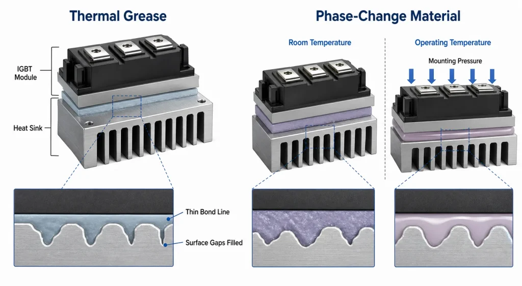
Thermal grease has long been used between IGBT modules and cooling components because it wets the mating surfaces well and can produce a thin bond line. Under mounting pressure, the grease spreads across the interface and fills microscopic voids. When the application process is controlled, it can provide low contact resistance without requiring a thick pad.
The practical result depends strongly on coating quality. An uneven layer can leave dry areas or create locally thick regions. Both conditions disturb heat flow and may cause temperature differences between chips within the same module. Controlled dispensing, stencil printing or screen printing can improve repeatability, but the selected process must be validated for the grease rheology, module footprint and production volume.
Long-term reliability must also be considered. Repeated thermal expansion and contraction can cause grease to move away from highly loaded regions, a phenomenon commonly described as pump-out. Base-oil separation, drying and contamination can also change interface performance over time. These risks vary considerably between formulations and operating conditions, so qualification should rely on thermal cycling and application-specific aging tests rather than on conductivity data alone.
Phase-Change Materials for IGBT Cooling
A phase-change thermal interface material is generally solid or firm at room temperature, which makes it easier to handle as a pre-applied film or pad. When the assembly reaches its activation temperature, the material softens and flows under mounting pressure. It then conforms to the mating surfaces and fills the microscopic gaps in a manner similar to thermal grease.
This behavior can improve production cleanliness and control the amount of material applied to each module. A preformed layer is also easier to transport and position than wet grease. Once properly conditioned, a suitable phase-change material can provide stable interface performance through repeated operating cycles.
The material must nevertheless be matched to the application. Its phase-transition range should be compatible with the normal operating temperature, and the mounting system must provide enough pressure for the softened material to wet the surfaces. Thickness tolerance, electrical insulation, edge flow, reworkability and long-term stability must all be evaluated. A phase-change material is not automatically the better choice simply because it has a higher thermal-conductivity value.
Bond-Line Thickness, Flatness and Mounting Pressure
The interface material works together with the mechanical design. Baseplate flatness, cold-plate flatness, surface finish, screw position and tightening sequence all influence the final bond-line thickness. A cooling component with excellent internal channels can still deliver disappointing results if its mounting surface is distorted or if pressure is concentrated near the fasteners.
Mounting torque should follow the IGBT manufacturer’s instructions. Tightening the screws gradually and in the specified sequence helps distribute pressure across the module. Excessive torque can bend the baseplate or damage the package, while insufficient torque increases contact resistance and makes the interface more sensitive to vibration and thermal cycling.
The heat sink or cold plate also needs enough local stiffness to maintain contact. This is particularly important for large modules and thin cold plates, where coolant pressure, machining stress or mounting loads can affect flatness. The mechanical and thermal designs should therefore be reviewed together.
Choosing Between an Air-Cooled Heat Sink and a Liquid Cold Plate
The thermal interface cannot compensate for an undersized cooling component. Once heat crosses the module-to-sink interface, the heat sink or cold plate must spread and reject it efficiently. An air-cooled heat sink may be appropriate when the loss density is moderate and sufficient space and airflow are available. Fin geometry, fan performance and enclosure airflow determine the actual sink-to-air resistance.
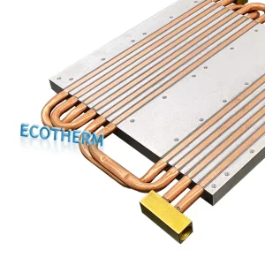
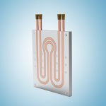
A liquid cold plate is more suitable when the heat flux is high, the available space is limited or the application requires closer temperature control. The channel layout should bring coolant beneath the principal heat sources while maintaining an acceptable pressure drop. Coolant flow rate, inlet temperature, material compatibility, corrosion protection, sealing and leak testing are part of the thermal solution.
For either method, the cooling surface should be designed around the module footprint rather than treated as a generic flat plate. Heat spreading, mounting holes, electrical clearances and neighboring components can all influence the usable geometry.
How to Validate the Completed Thermal Assembly
A reliable design should be checked at the operating conditions that create the highest junction temperature, not merely at rated power under room-temperature conditions. The validation should compare calculated losses with measured case, heat-sink and coolant temperatures. When direct junction-temperature measurement is not practical, a validated thermal model can be used to estimate Tj from electrical loss and transient thermal impedance.
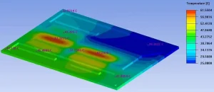
Temperature uniformity is as important as the average value. A local hot spot may indicate uneven TIM coverage, poor flatness, insufficient mounting pressure or a cold-plate channel that does not align with the heat source. Thermal cycling can then be used to determine whether the interface resistance remains stable over time.
For production, the application method and assembly controls should be documented. A thermal solution is not complete until the coating thickness, mounting sequence and inspection criteria can be repeated consistently from one unit to the next.
Frequently Asked Questions
Does a higher thermal-conductivity TIM always cool an IGBT better?
No. Effective interface resistance also depends on bond-line thickness, surface wetting, mounting pressure, void content and long-term stability. A lower-conductivity material applied in a thinner and more uniform layer can outperform a nominally higher-conductivity material in the finished assembly.
How much thermal grease should be applied to an IGBT module?
The correct amount is the minimum required to create a continuous layer and fill the surface irregularities after mounting. The target thickness should be established through supplier guidance, controlled trials and thermal validation. A visibly thick layer is not evidence of better cooling.
Is phase-change material better than thermal grease?
Neither material is universally superior. Thermal grease can achieve a very thin bond line and low initial contact resistance, while phase-change material can offer cleaner handling and more consistent pre-application. The correct choice depends on temperature range, pressure, production process, service life and rework requirements.
Why does an IGBT module overheat even when the heat sink is large?
The problem may be located at the interface rather than in the overall heat-sink size. Uneven TIM, poor surface flatness, incorrect torque, inadequate airflow, high coolant temperature or underestimated switching loss can all raise junction temperature.
What information is needed to design an IGBT cooling component?
The design should be based on the module drawing, loss distribution, maximum allowable junction temperature, load profile, ambient or coolant temperature, installation envelope, mounting requirements and expected production quantity. For liquid cooling, coolant type, flow rate and allowable pressure drop are also required.
Request a Custom IGBT Cooling Solution
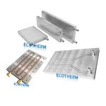
Ecothermgroup develops custom heat sinks and liquid cold plates for power electronics applications. To evaluate an IGBT cooling project, provide the module drawing, estimated heat loss, operating temperature range, available space, mounting arrangement, coolant conditions and expected quantity. These inputs allow the cooling surface, heat-spreading path and fluid or airflow requirements to be reviewed as one system. Visit the Ecothermgroup website to discuss your application.