Why Precision Machining is the Deciding Factor in Heat Sink Efficiency
In high-power electronic design—spanning from EV powertrain inverters and AI server racks to medical imaging equipment—thermal management is no longer a secondary consideration. It is a primary bottleneck.
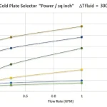
Engineers spend weeks running computational fluid dynamics (CFD) simulations in software like ANSYS or Icepak to optimize fin geometry, air-flow velocity, and material selection. However, a common discrepancy arises in practical hardware development: the thermal performance of a physical prototype often underperforms compared to its idealized simulation by 15% to 25%.
Why does this gap exist? The answer rarely lies in faulty design. Instead, it lies in the micro-level geometric deviations introduced during manufacturing. Here is an engineering analysis of how precision CNC machining bridges the gap between theoretical thermal models and actual hardware performance.
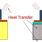
1. Minimizing Micro-Air Gaps: Surface Flatness and Roughness (Ra)
The primary source of thermal resistance (Rth) in any electronics assembly occurs at the interface between the heat source (such as an IGBT module or CPU chip) and the heat sink base plate. Because air has an extremely low thermal conductivity (approximately 0.026 W/m·K), even microscopic gaps between these two surfaces act as thermal insulators.
While Thermal Interface Materials (TIMs) like grease, pads, or phase-change materials are used to fill these gaps, TIMs themselves have much lower thermal conductivity than aluminum (around 200 W/m·K) or copper (around 400 W/m·K). Therefore, the ideal engineering goal is to minimize the thickness of the TIM layer by maximizing direct metal-to-metal contact.
Surface Flatness:
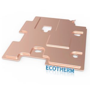
If a heat sink base plate exhibits warping or concavity after machining, the TIM layer becomes unevenly distributed. Precision CNC face milling handles this by maintaining flatness tolerances within <= 0.02 mm across the entire mating surface, ensuring uniform pressure distribution.
Surface Finish (Ra):
High-speed fly cutting and optimized spindle-to-feed ratios reduce surface roughness to Ra 0.4 – 0.8 microns. This eliminates the deep microscopic peaks and valleys that trap air, allowing for an ultra-thin, highly efficient TIM bond line.
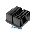
2. High Aspect Ratio Fin Geometry and Structural Stability
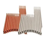
To maximize heat dissipation within a constrained physical volume, modern heat sinks require thin, densely packed fins (high-density pin fins or straight fins). This introduces a high aspect ratio challenge for standard machining operations.
When milling aluminum 6061 or pure copper down to fin thicknesses of 0.5 mm or less, the material becomes highly susceptible to tool pressure and thermal stress during cutting. Without strict process control, two manufacturing defects occur:
Fin Chattering: Micro-vibrations cause structural deformation, leading to uneven fin spacing. This alters the calculated aerodynamics and air-flow velocity through the heat sink channels, resulting in localized hotspots.
Burr Formation: Heavy burrs at the top edges of the fins restrict laminar airflow, causing unwanted turbulence and micro-pressure drops.
To counteract this, specialized facilities implement optimized tool paths, customized carbide cutters, and specific flood-cooling strategies to ensure consistent wall thickness, straightness, and zero-burr finishes on complex geometries.
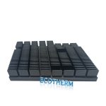
3. Machining Challenges in Dissimilar Material Hybrids
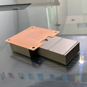
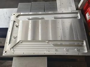
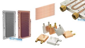
To achieve an optimal balance between cost, weight, and performance, many advanced thermal solutions utilize hybrid structures—such as copper blocks or vapor chambers embedded into an aluminum base plate. Copper provides rapid localized heat spreading directly under the die, while aluminum handles the bulk heat dissipation via its lighter fins.
The machining bottleneck here lies in the Mechanical Interface. If the slot milled into the aluminum base does not perfectly match the dimensions of the copper insert, an air pocket or mechanical stress point is created.
Furthermore, copper and aluminum have vastly different machinability ratings, thermal expansion coefficients, and cutting behaviors:
Copper (C101/C110) is highly ductile and “gummy,” tending to adhere to the cutting edge and cause rapid tool wear.
Aluminum (6061-T6) chips easily and requires high surface speeds.
Machining these two materials after they have been friction-stir welded or bonded requires rigid workholding and precise depth control (often within +/- 0.01 mm) to prevent any step-height variations across the continuous multi-material joint.
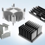
4. Empirical Data: CNC Machining vs. Die Casting for Thermal Integrity
When scaling from prototype to production, choosing the manufacturing process drastically alters the thermal integrity of the raw material.

Performance Metric | Precision CNC Machining (From Billet) | Standard Die Casting |
Material Density | 100% Solid Billet (No voids) | Risk of internal porosity/air bubbles |
Fin Thickness Limit | Down to 0.5 mm with high rigidity | Limited by molten metal flow limits |
Thermal Conductivity | Retains 100% of alloy specification | Reduced by impurities and micro-voids |
Geometric Tolerance | Generates tight, repeatable linear dimensions | Subject to thermal shrinkage and warping |
For mission-critical applications where thermal failure is not an option, components machined directly from extruded or forged stock outperform cast components due to the total absence of internal porosity, which otherwise acts as an internal thermal barrier
Conclusion: DFM as the Bridge
An excellent thermal design is only as good as the physical component that replicates it. For hardware engineers developing complex heat sinks, cold plates, or customized enclosures, collaborating with a manufacturing team that understands Geometric Dimensioning and Tolerancing (GD&T) for thermal applications is critical.
Integrating Design for Manufacturing (DFM) early in the prototyping phase with a dedicated precision provider like DEK CNC Machining Services ensures that tight tolerances are achieved efficiently, cost-effectively, and reliably at scale.