TEC Design Selection and Simulation Application
Preface
Thermoelectric Coolers (TEC), with their advantages such as precise temperature control, lack of vibration, and environmental friendliness, have become a core technology in fields like optical communications, medical equipment, and electronics thermal management. Based on the technical principles of TEC and practical engineering experience, this article outlines the TEC selection methodology, covering the interpretation of key parameters, the selection process, verification examples, and simulation considerations. Following this process will enable more efficient TEC selection and determination of its thermal design goals.
I. TEC Technical Principles
TEC (Thermoelectric Cooler, or semiconductor cooler) is a solid-state cooling technology based on the Peltier effect, which uses a direct current to drive semiconductor material for directional heat transfer.
Structural Characteristics
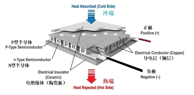
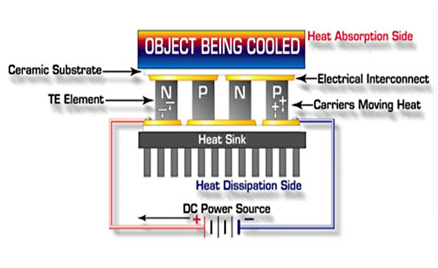
The interior is composed of multiple thermocouples made of N-type and P-type bismuth telluride semiconductors.
Both the cold and hot surfaces are covered with an electrical insulator, typically a ceramic plate.
Working Characteristics:
When current is applied, the cold side absorbs heat (cooling), and the hot side releases heat (heat dissipation).
Reversing the current direction switches the cooling/heating mode, enabling bidirectional temperature control.
A single-stage TEC can achieve a temperature difference of $60^{\circ}\text{C}$–$70^{\circ}\text{C}$. Multi-stage stacking allows for wide-range temperature control from $-130^{\circ}\text{C}$ to $90^{\circ}\text{C}$.
Core Advantages:
| Advantage Feature | Specific Manifestation |
| Precise Temperature Control | Temperature control accuracy up to $\pm 0.1^{\circ}\text{C}$, millisecond-level response speed. |
| No Mechanical Moving Parts | No compressor, no vibration, no noise, long lifespan (no wear and tear). |
| Environmental Friendliness | Requires no refrigerants (e.g., Freon), avoiding leakage and pollution. |
| Miniaturization and Flexibility | Compact size, customizable shapes (e.g., micro-chip, annular), supports installation at any angle. |
| Bidirectional Temperature Control | The same device switches between cooling/heating modes by reversing the current direction, eliminating the need for an extra heating system. |
| Wide Operating Environment | Stable operation in vacuum and zero-gravity environments (e.g., spacecraft). |
Application Fields: Due to the above characteristics, TECs are indispensable in optical communications, medical equipment, electronics thermal management, dehumidification systems, and portable temperature control scenarios.
II. Key Parameters in TEC Specifications
TEC specifications typically provide key parameters at 25°C and 50°C, as shown below:
| Parameter | Hot Side Temperature Th = 25°C | 50°C | Description |
|---|---|---|---|
| Maximum Cooling Capacity Qcmax (W) | 64.0 | 68.5 | Thermal power at I = Imax and ΔT = 0 |
| Maximum Temperature Difference ΔTmax (°C) | 68.0 | 72.0 | Temperature difference at Qc = 0 and I = Imax |
| Maximum Current Imax (A) | 7.5 | 7.5 | Current at ΔT = ΔTmax or Qc = Qcmax |
| Maximum Voltage Umax (V) | 15.4 | 16.9 | Voltage at ΔT = ΔTmax and I = Imax |
| AC Resistance (1 KHz) (Ω) | 1.65 | 1.82 | AC resistance of the module at specified temperature |
| Performance Tolerance | ±12% | Product performance control standard |
These parameters can be used as key input parameters for simulation software. Taking FloTHERM as an example, the parameters can be entered separately for Hot Side 1 at 25°C and Hot Side 2 at 50°C.
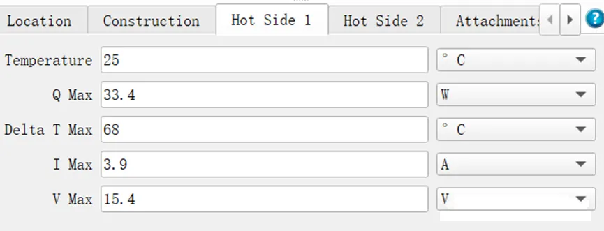
In addition to the key parameters, the specification sheet usually also provides the dimensional parameters of the TEC. The cold-side dimensions should be as close as possible to the size of the heat source that needs to be cooled.
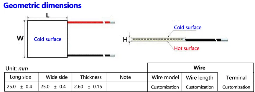
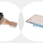
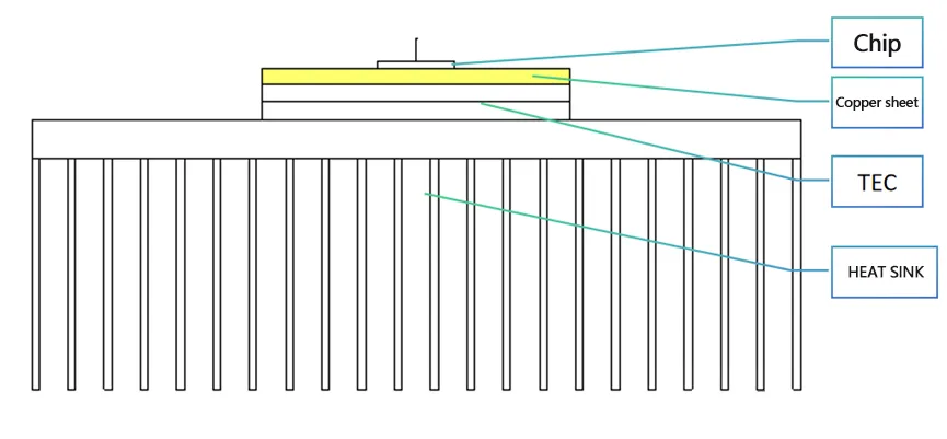
If the TEC cold-side dimensions are much larger than the heat source, a high-thermal-conductivity metal such as a copper plate should be added to the TEC cold side for heat spreading. The schematic diagram is shown below.
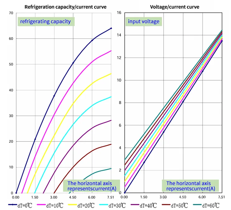
To facilitate selecting a suitable TEC when performing temperature control with a TEC, the specification sheet usually provides cooling capacity curves at different temperature differences and currents for the hot and cold sides. Based on these performance curves, a preliminary TEC selection can be made.
3. TEC Selection Process
Taking chip temperature control as an example, the step-by-step process is as follows:
(1) Estimate total cooling capacity:
Qtotal=P1 (chip power consumption)+P2 (heat transfer from surrounding components)Q_{\text{total}} = P_1 \text{ (chip power consumption)} + P_2 \text{ (heat transfer from surrounding components)}Qtotal=P1 (chip power consumption)+P2 (heat transfer from surrounding components)
(2) Determine the required temperature difference:
ΔT=T2 (ambient temperature)−T1 (target temperature)\Delta T = T_2 \text{ (ambient temperature)} – T_1 \text{ (target temperature)}ΔT=T2 (ambient temperature)−T1 (target temperature)
(3) Set a preliminary TEC temperature difference:
ΔTTEC=ΔT+30∘C(to ensure heat dissipation margin)\Delta T_{\text{TEC}} = \Delta T + 30^\circ C \quad (\text{to ensure heat dissipation margin})ΔTTEC=ΔT+30∘C(to ensure heat dissipation margin)
Optimization recommendation:
ΔTTEC\Delta T_{\text{TEC}}ΔTTEC is preferably controlled around 40°C.
If it is too low → heatsink design becomes difficult.
If it is too high → TEC efficiency decreases and more TECs are required.
(4) TEC model selection:
Based on the specification sheet curves, match ΔTTEC\Delta T_{\text{TEC}}ΔTTEC and QtotalQ_{\text{total}}Qtotal to select a model that meets the cooling capacity.
Calculate the TEC’s own heat generation QtecQ_{\text{tec}}Qtec (based on current and voltage).
(5) Heatsink selection:
Total heat dissipation=Qtec+Qtotal\text{Total heat dissipation} = Q_{\text{tec}} + Q_{\text{total}}Total heat dissipation=Qtec+Qtotal
Calculate required heatsink thermal resistance RRR:
R=ΔTHSTotal heat dissipation(ΔTHS is usually 20°C)R = \frac{\Delta T_{\text{HS}}}{\text{Total heat dissipation}} \quad (\Delta T_{\text{HS}} \text{ is usually 20°C})R=Total heat dissipationΔTHS(ΔTHS is usually 20°C)
4. TEC Cooling Selection Example
The following parameters are used to validate the process:
Key Parameters
| Parameter | Value |
|---|---|
| Chip Power Consumption P1P_1P1 | 20 W |
| Heat Transfer from Surrounding Components P2P_2P2 | 2 W |
| Target Temperature T1T_1T1 | 25°C |
| Ambient Temperature T2T_2T2 | 35°C |
| Total Cooling Capacity QtotalQ_{\text{total}}Qtotal | 22 W |
Selection Process:
(1)
ΔTTEC=(35−25)+30=40∘C\Delta T_{\text{TEC}} = (35 – 25) + 30 = 40^\circ CΔTTEC=(35−25)+30=40∘C
(Within the optimal 30–40°C range)
(2) Select a TEC model:
At ΔTTEC=40∘C\Delta T_{\text{TEC}} = 40^\circ CΔTTEC=40∘C,
Qmax=28 W>22 WQ_{\text{max}} = 28 \text{ W} > 22 \text{ W}Qmax=28 W>22 WOperating current I=5 AI = 5 \text{ A}I=5 A, voltage V=10 VV = 10 \text{ V}V=10 V
QTEC=50 WQ_{\text{TEC}} = 50 \text{ W}QTEC=50 W
TEC self-heating:
(3) Hot-side heat dissipation power:
22 W+50 W=72 W22 \text{ W} + 50 \text{ W} = 72 \text{ W}22 W+50 W=72 W
(4) Heatsink thermal resistance RRR:
Assume ΔTHS=20∘C\Delta T_{\text{HS}} = 20^\circ CΔTHS=20∘C
(reserving 10°C for TIM and chip case temperature rise)
R = \frac{20^\circ C}{72 \text{ W}} \approx 0.277^\circ C/\text{W}
]
5. TEC Application & Simulation Precautions
Usage Restrictions
Condensation/frost prevention is required on the cold side.
The hot side must be actively cooled (air cooling / liquid cooling).
Exceeding limits on temperature, current, and voltage is strictly prohibited.
DC power supply only.
Flotherm Simulation Setup
TEC module operates along the local coordinate Z0 direction
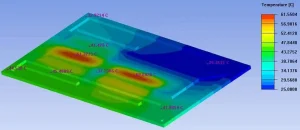
(Z0 reference plane is the cold side, which must contact the heat source).After installation, distinguish cold/hot sides using Monitor Points.