Cold Plate Design Guide (Part 1): Key Basics for Efficient Thermal Management
This guide covers cold plate structure, material selection, and flow-path choice. It explains how to select a practical construction before detailed thermal and hydraulic sizing begins.
For thermal resistance, coolant flow rate, pressure drop, and a complete worked example, continue to Part 2: Cold Plate Design Calculations.
Introduction
The next generation of GPUs and switch chips will each exceed 1000W in power consumption.For example, the GB200 (1 Grace CPU + 2×B200) has a total thermal design power (TDP) of 2700W. Air cooling becomes extremely challenging for such high-power chips. Driven by NVIDIA, cold plate liquid cooling has now entered large-scale deployment in liquid-cooled servers within data centers.
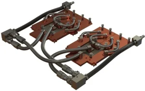
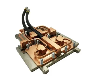
Figure 1 GB200 Cold Plate
1.GPU and Switch Chips:
High Power and Heat Flux Density Devices in AI Server Liquid Cooling Design
Both GPUs and switch chips are high-power, high-heat-flux-density devices (exceeding 50W/cm², with local hotspots reaching up to 150W/cm²). Typically, the temperature rise (Tc) of these chips should not exceed 40°C, with GPUs often requiring a rise of no more than 30°C. To meet the thermal management demands of such chips, the most commonly used cooling solution in the industry is the microgroove cold plate with scalloped teeth.
Designing a cold plate with extremely low thermal resistance (<0.03°C/W) and flow resistance not exceeding 20 kPa is a key aspect of AI server liquid cooling design. Even with cold plate-based liquid cooling, if the design is not optimized, the performance may not meet the required specifications.
To better support the thermal dissipation needs of high-performance chips, researching the design of cold plates is essential. This article will combine past development experiences and provide a detailed guide on how to design a cold plate for data centers. The article will be divided into three sections:
Fundamentals: This section will summarize the foundational heat transfer theories involved in cold plate performance analysis, which are essential for quick theoretical calculations to guide the cold plate design.
Thermal Calculation: In this section, we will discuss the key thermal design technologies for cold plates: low thermal resistance solutions, scalloped tooth parameters, and groove dimensions.
Cold Plate Reliability: Here, we will explore methods to reduce flow resistance, enhance cold plate pressure tolerance, and ensure long-term reliability of cold plates, along with the impact on the liquid cooling system.
2. Cold Plate Structure
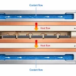
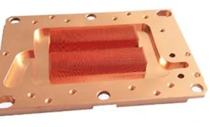
Figure 2 shows the internal structure of the cold plate designed for high-power chips like GPUs in data centers. The central area of the cold plate, which comes into contact with the chip, is equipped with scalloped microgroove fins.
The cold plate is typically made of copper (thermal conductivity: 385W/mK @ 20°C), with fin thickness generally not exceeding 0.5mm and fin spacing not exceeding 0.5mm. To facilitate manufacturing, the scalloped fins are usually parallel and flat.
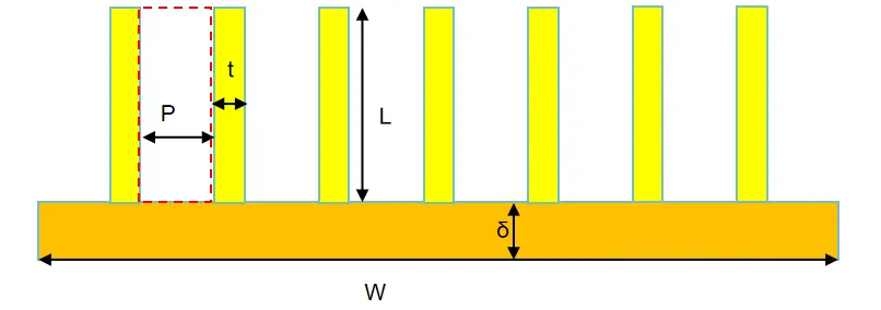
From the cross-section of the microgroove, the structure of the fins is shown in Figure 3. The fin thickness is denoted as t, the fin height as L, the fin spacing as P, the substrate thickness as δ, and the width of the fin channel area as W.
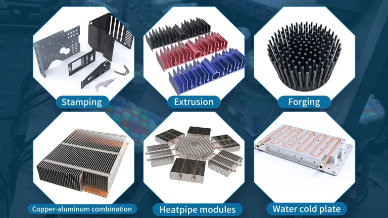
Choose the Cold Plate Construction
| Construction | Best suited for | Main advantage | Main limitation |
|---|---|---|---|
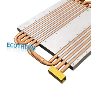
| Tube-in-plate | Moderate heat loads, flexible routing and cost-sensitive projects | Simple construction and flexible tube path | Tube-to-plate contact adds thermal resistance |
| Gun-drilled | Robust plates with straight or intersecting channels | Strong solid-plate structure | Limited internal routing freedom |
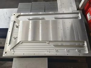
| Machined-channel with FSW | Aluminum plates requiring flexible channels and a strong cover joint | Good balance of strength and channel freedom | Welding path and distortion must be reviewed |
| Vacuum-brazed | Complex channels, internal fins and concentrated heat sources | Greater internal design freedom | Brazing quality, cleanliness and distortion need control |
| Fin-enhanced construction | High local heat flux where additional surface area is required | Increased internal heat-transfer area | Higher pressure drop and contamination sensitivity |
Construction selection should be based on the heat-source map, coolant, allowable pressure drop, mechanical envelope and production requirements—not thermal conductivity alone.
3. Flow Characteristics Inside the Cold Plate
According to the current cold plate structure, the liquid inside the cold plate flows through multiple parallel microgrooves when passing over the fins. Since the fin spacing P is typically ≤ 0.5mm (usually 0.2mm), and the fin height L is ≥ 3mm, the ratio of L/P is generally much greater than 15. As a result, the flow between the fins inside the cold plate follows a high aspect ratio channel flow.
The equivalent hydraulic diameter of the cold plate is given by:
Dh = 2P * L / (P + L)
Since L/P is typically greater than 15, the hydraulic diameter Dh is approximately 2P.
Assuming the fluid enters and exits the cold plate from one side, with a flow rate Q, the average flow velocity between the fins is:
V = Q * (1 + t / P) / (W * L)
The Reynolds number between the fins is:
Re = ρ * V * Dh / μ
Based on the cooling flow rate and dimensions of the cold plate, the flow velocity between the fins is usually V < 0.1 m/s, and from calculations, we can see that Re < 2000, indicating laminar flow.
According to the conclusions derived from the earlier system flow resistance analysis and combining with the flow resistance formula, there are two methods to reduce the flow resistance between the fins:
Reduce the flow velocity between the fins (V), which can significantly lower the flow resistance between the fins.
Reduce the fin length in the flow direction, which can significantly lower the flow resistance between the fins.
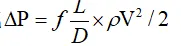
Length of the inlet section in laminar flow
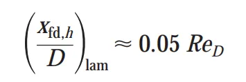
For Re = 800 and D = 0.4mm, the entrance length is approximately 16mm. Typically, the length of the cold plate in the flow direction exceeds 16mm, ensuring that fully developed laminar flow is generally achieved within the cold plate.
Select the Flow-Path Layout
| Flow-path layout | Use when | Watch for |
|---|---|---|
| Straight or parallel | Low pressure drop and uniform heat distribution are priorities | Flow maldistribution between branches |
| Serpentine | A single controlled flow path is preferred | Higher pressure drop over long paths |
| Split-flow | Pressure drop must be reduced across a large active area | Manifold balance and outlet symmetry |
| Local fin or pin enhancement | Heat is concentrated in a limited area | Contamination sensitivity and pressure drop |
| Tube routing | Heat sources are distributed and moderate heat flux is acceptable | Bend radius and tube-to-base contact |
TIPS:
The flow path should cover the heat-source area without creating an unnecessary bypass between the inlet and outlet. Mounting holes, sealing lands and port locations must be considered before the channel is finalized.
Shorter flow paths generally reduce pressure drop, while narrower channels and added internal surface area may improve heat transfer at the cost of higher pumping demand. The final choice must balance temperature uniformity, pressure drop and manufacturability.
4. Heat Transfer Characteristics Between the Fins
In the fully developed laminar flow region, the Nusselt number (Nu) is a constant value, which only changes with the aspect ratio of the channel.
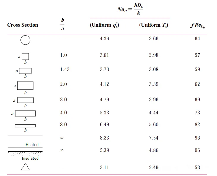
According to the definition of the Nusselt number (Nu), the convective heat transfer coefficient h in the channel is given by:
h = Nu * k / Dh,
where k is the thermal conductivity of the fluid and Dh is the hydraulic diameter.
Since the flow between the fins is in the fully developed laminar flow region, the convective heat transfer coefficient h inside the cold plate is generally not influenced by the flow velocity V. To increase h, there are two potential solutions:
Increase the thermal conductivity of the fluid (k)
Reduce the equivalent hydraulic diameter (Dh)
5. Heat Transfer Efficiency of the Fins
The heat transfer in microgroove cold plates is surface-enhanced heat transfer. The one-dimensional model for surface-enhanced heat transfer is shown in Figure 5.
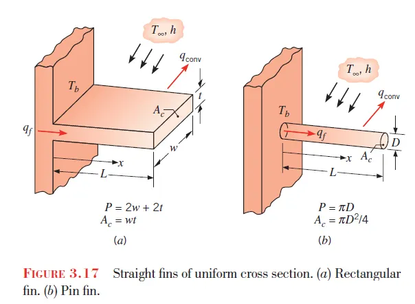
According to heat transfer theory, assuming the fin tip is insulated, the maximum heat transfer power of the fin is

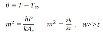
The maximum heat transfer power of the fin qmax = hPLΘb,
The fin heat transfer efficiency
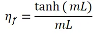
When Tanh(mL) = 0.99, it can be assumed that further increasing the fin height has almost no impact on the heat transfer from the extended surface area. At this point, mL = 2.65.
Assuming a fin thickness of 0.2mm and the fins are made of pure copper with a thermal conductivity k = 385 W/mK, the maximum fin height is approximately 7.3mm.
Choose the Cold Plate Material
Copper or Aluminum
| Factor | Aluminum | Copper |
|---|---|---|
| Weight | Lower | Higher |
| Thermal conductivity | Moderate | Higher |
| Machining | Good | Good, but heavier and generally more expensive |
| Typical use | Large plates, EV systems, industrial equipment | Concentrated heat sources and compact high-performance plates |
| Joining options | FSW, vacuum brazing and mechanical assembly | Brazing, soldering and other project-specific joining methods |
Coolant and Material Compatibility
Material selection must consider every wetted component in the loop, including the cold plate, tubing, fittings, pump, heat exchanger and coolant. Mixing dissimilar metals without an appropriate coolant formulation can increase galvanic-corrosion risk.
Before release, confirm the coolant chemistry, inhibitor package, operating temperature and maintenance interval with the coolant and system requirements.
6. Total Effective Surface Area of the Fins
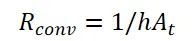
Assuming the cold plate has N fins, with the area of a single fin being Af and the fin efficiency being ηf, the heat transfer area of the substrate excluding the fins is Ab. The total effective heat transfer area is:

The total convective heat resistance is
7. Conclusion
This article is the foundational section on cold plate design, primarily summarizing and analyzing the relevant theoretical content for calculating flow resistance and thermal resistance required for cold plate design.
Subsequent sections will build on the above analysis and, in conjunction with the flow and heat transfer characteristics of microgroove cold plates, will further explore methods to enhance cold plate performance and reduce thermal resistance.
Need help reviewing a cold plate concept?
Send Ecothermgroup your heat-source map, coolant conditions, pressure-drop limit and mechanical drawing. Our engineers can review the construction method, material, flow path and manufacturing feasibility before prototyping.
Already selected the structure? Continue to Part 2 for thermal resistance, flow-rate and pressure-drop calculations.