how to calculate heat sink thermal resistance
Many power electronics designs struggle with excess heat, which can reduce performance, shorten lifespan, or even cause failure. This article explains how to calculate heat sink thermal resistance so you can choose the right cooling solution and keep your components operating safely. Understanding how to calculate heat sink thermal resistance helps you make better thermal design decisions from the start, and it gives Ecothermgroup a practical framework for selecting effective cooling solutions.
Takeaway
- Start with the allowable temperature rise: define ambient temperature, the maximum device junction temperature, and total power dissipation before you size the heatsink.
- Use the thermal resistance chain to work backward from junction to ambient, subtracting the device and interface thermal resistances to find the heatsink resistance you can allow.
- Treat thermal resistance in degrees C per watt and keep the calculation conservative by using worst-case power, ambient conditions, and tolerance values.
- Account for real-world losses in the thermal path, including mounting quality, thermal interface material, airflow, enclosure effects, and nearby heat sources.
- Choose a heatsink with a thermal resistance lower than the calculated maximum, since datasheet values are often measured under ideal conditions.
- Validate the selected heatsink against the actual operating profile, not just a single steady-state number, especially for pulsed loads or variable duty cycles.
- Use a stepwise selection workflow: define limits, calculate the target resistance, compare candidate parts, then verify temperature in the final mechanical and airflow environment.
Thermal Resistance Basics
To understand how to calculate heat sink thermal resistance, start with the full thermal resistance network, not just the heat sink itself. In power electronics, heat moves from the junction to the case, then through the interface to the sink, and finally from the sink to ambient air. This is why required heat sink thermal resistance is usually calculated from the maximum junction temperature, the expected ambient air temperature, and the power dissipation at the worst load condition. A common first-pass method is to subtract the known junction-to-case thermal resistance and case-to-sink thermal resistance from the total thermal budget, then solve for the remaining sink-to-ambient thermal resistance. That remaining value is the heat sink thermal resistance formula most designers use for heat sink sizing.
| Thermal path | What it means in the calculation |
|---|---|
| Junction-to-case thermal resistance | Heat flow inside the package before it reaches the mounting surface |
| Case-to-sink thermal resistance | Contact loss from grease, pad, flatness, and mounting pressure |
| Sink-to-ambient thermal resistance | The heat sink performance needed to keep the device below limit |
Key Thermal Paths
These three paths work together. ON Semiconductor’s mounting guidance shows that contact resistance and assembly quality can change the real result more than many people expect. In practice, a heat sink rated at a low degrees Celsius per watt value in a catalog may perform worse after installation if airflow is blocked or the interface material is poorly applied. That is why Ecothermgroup and other suppliers usually recommend checking the final assembly, not only the bare sink.
The standard baseline is steady-state sizing. If a device has 25 W of power dissipation, a 100°C maximum junction temperature, and a 40°C ambient air temperature, the thermal rise available to the whole chain is 60°C. After subtracting the junction-to-case and interface losses, the remaining sink-to-ambient thermal resistance must be low enough to keep the junction within limit. Forced-air cooling lowers that required value further, while natural convection usually needs a larger sink.
Core Terms
Several terms are often confused, and that can lead to poor junction temperature calculations. Junction-to-case thermal resistance describes the package itself. Case-to-sink thermal resistance describes the contact layer. Sink-to-ambient thermal resistance describes the heat sink and surrounding air as one system. The latter is not a fixed property, because mounting orientation, enclosure spacing, surface finish, and airflow all affect it.
- Use worst-case power dissipation, not average load.
- Use the hottest ambient air temperature expected in service.
- Add margin for interface resistance and airflow restriction.
- Check vendor curves against the actual build before final selection.
Texas Instruments notes that some package thermal metrics can be misunderstood, especially when designers treat junction-to-case values as if they alone define heat sink selection. They do not. A complete thermal resistance network gives a more realistic thermal budget and reduces the risk of overheating during high-load bursts. For that reason, the required heat sink thermal resistance should be treated as a design target, then validated against measured data or simulation before release.
Input Data
To calculate required heat sink thermal resistance, start with the three inputs that drive the thermal budget: device power dissipation, maximum junction temperature, and ambient air temperature. DigiKey’s selection method and All About Circuits’ calculator both use the same core idea, because the heat sink thermal resistance formula only works when you know how much heat must move from the semiconductor to the air. In practice, designers should use power loss, not input power, since the actual dissipation in the device can be much lower or higher than the electrical load appears to be on paper.
The thermal resistance network is usually split into junction-to-case thermal resistance, case-to-sink thermal resistance, and sink-to-ambient thermal resistance. ON Semiconductor’s mounting guide stresses that the interface terms matter, because contact quality, grease, pad choice, and mounting pressure all change the result. Texas Instruments also notes that datasheet thermal metrics can be misunderstood, so the published junction-to-case number should be treated as a starting point rather than a final answer for heat sink sizing.
| Input | Why it matters | Typical source |
|---|---|---|
| Power dissipation | Defines the heat that must be removed | Device loss estimate, not input power |
| Maximum junction temperature | Sets the upper limit for the junction temperature calculation | Semiconductor datasheet |
| Ambient air temperature | Sets the starting point for sink-to-ambient thermal resistance | Worst-case enclosure or room condition |
| Interface resistance | Captures case-to-sink thermal resistance in real mounting | Pad, grease, clamp, or screw method |
Device Power Loss
For how to calculate heat sink thermal resistance, device power loss is the first value to pin down. A power transistor, regulator, or diode rarely turns all electrical input into useful output, so the thermal load must come from measured or estimated loss. DigiKey’s step-by-step method uses the expected dissipation directly, and that is the right habit when you are doing first-pass heat sink selection. For example, a 20 W loss with a 30 degrees Celsius per watt target is a very different case from a 20 W electrical input with only 6 W of real heat.
In practical work, engineers often add margin for switching spikes, load drift, and aging. That margin is not optional when the design must survive summer ambient conditions, restricted airflow, or a fan that may slow down over time. Ecothermgroup and other heat sink suppliers generally recommend sizing from worst-case dissipation, because undersizing leaves no room for mounting variation or manufacturing spread.
- Estimate the worst-case dissipation at full load.
- Include converter or switching losses, not only load power.
- Apply a margin for tolerance, airflow, and aging.
Temperature Limits
The second input is the maximum junction temperature, which defines how much temperature rise the thermal resistance network can tolerate. Common silicon parts are often rated to 125 C or 150 C junction limits, but the usable design target is usually lower after you subtract interface losses and expected variation. ON Semiconductor’s guidance is useful here because it separates junction-to-case from case-to-sink, making the thermal budget easier to allocate.
A simple check is to compare the allowed rise above ambient with the total heat flow. If the junction limit is 125 C, ambient is 45 C, and the device loss is 10 W, then every stage must fit inside an 80 C rise. That is why the case-to-sink thermal resistance and the sink-to-ambient thermal resistance both matter in the final selection. Use the datasheet limit, then reduce it for reliability if the application is high duty, sealed, or hard to service.
Ambient Conditions
Ambient air temperature often decides whether a design passes or fails. A heatsink that works at 25 C may be too small at 50 C inside an enclosure. All About Circuits frames this well in calculator form: the ambient value is the reference point for the entire junction temperature calculation, so it should reflect the hottest realistic environment, not a comfortable bench test. Forced-air cooling can lower the required heat sink thermal resistance sharply, but only if the airflow is reliable and the fins are oriented correctly.
Use ambient conditions that match the real system: sealed box, open frame, vertical install, or fan-cooled chassis. A practical input-data check is below.
| Condition | Input to use | Risk if ignored |
|---|---|---|
| Open bench test | Room temperature only | Overstates cooling margin |
| Enclosed cabinet | Internal air temperature | Undersized sink selection |
| Forced-air cooling | Lowest expected airflow performance | Fan failure leads to overheating |
Good input data is the difference between a rough guess and a defensible heat sink thermal resistance formula. When the numbers are complete, the result becomes a clear sink-to-ambient thermal resistance target in degrees Celsius per watt, with enough margin to support the real operating envelope.
Calculation Method
To calculate heat sink thermal resistance for power electronics, start with the thermal resistance network from junction to ambient. In practice, engineers treat the path as a series chain: junction-to-case thermal resistance, case-to-sink or thermal interface resistance, and sink-to-ambient thermal resistance. This is the same first-pass method used in common heatsink selection guides, because it turns a complex thermal problem into a clear temperature rise budget. For Ecothermgroup-style heat sink sizing, the key is to use worst-case power dissipation and worst-case ambient air temperature, then solve for the maximum sink-to-ambient value the design can allow.
The basic heat sink thermal resistance formula is simple: allowable total thermal resistance equals the allowed temperature rise divided by power dissipation. The allowed temperature rise is maximum junction temperature minus ambient air temperature. From that total, subtract the datasheet junction-to-case thermal resistance and the case-to-sink thermal interface resistance. What remains is the required heat sink thermal resistance, usually expressed in degrees Celsius per watt. This is the main design target when you compare natural convection and forced-air cooling options.
Step-by-Step Formula
Manufacturers and thermal tools often frame the calculation the same way, but the terminology matters. Older datasheets may list junction-to-case values that do not describe every modern package path equally well, so the thermal resistance network should be read carefully and not used as a shortcut without context. That warning is common in semiconductor thermal notes and is one reason engineers check the package mounting method before finalizing heat sink selection. A small change in interface material, clamping force, or mounting flatness can shift the case-to-sink term enough to change the result.
| Term | Meaning |
|---|---|
| Maximum junction temperature | Upper limit from the device datasheet |
| Ambient air temperature | Worst-case temperature around the product |
| Power dissipation | Heat generated in watts under load |
| Junction-to-case thermal resistance | Internal package resistance |
| Case-to-sink thermal interface resistance | Contact resistance from pad, grease, or pad stack |
| Sink-to-ambient thermal resistance | Heat sink performance target |
A practical sequence is:
- Take the maximum junction temperature from the datasheet.
- Subtract the highest ambient air temperature expected in service.
- Divide the result by power dissipation to get the total allowable thermal resistance.
- Subtract junction-to-case thermal resistance and case-to-sink thermal interface resistance.
- Use the remaining value as the required heat sink thermal resistance.
Worked Example
Assume a power module has a maximum junction temperature of 150 C, a worst-case ambient air temperature of 40 C, and power dissipation of 60 W. The allowed temperature rise is 110 C, so the total allowable thermal resistance is 1.83 C/W. If the datasheet lists junction-to-case thermal resistance at 0.35 C/W and the mounting stack adds 0.15 C/W, the remaining sink-to-ambient thermal resistance is 1.33 C/W. That number becomes the target for heat sink sizing, and it shows why interface resistance cannot be ignored in real junction temperature calculation.
This is also where forced-air cooling changes the answer. A passive sink may not meet 1.33 C/W in a compact enclosure, while a finned sink with airflow may. In field use, many engineers compare a few candidate sinks at the same thermal budget rather than searching for one perfect part, because installation space, fan reliability, and dust buildup all affect the final choice. Online calculators from thermal tool providers follow the same logic and are useful for a quick sanity check before prototype testing.
Result Check
After solving for the required heat sink thermal resistance, check the result against the real operating profile. If the sink rating is only barely below the target, the design has little margin for a hotter ambient day, aging paste, or reduced airflow. In power electronics, a margin of 10 to 20 percent is commonly used in first-pass thermal design to protect the thermal budget. That margin is not a rule, but it is a practical way to avoid a design that passes only in ideal lab conditions.
| Check | Why it matters |
|---|---|
| Worst-case ambient | Protects the design in hot enclosures |
| Maximum power dissipation | Covers overload and high-load operation |
| Interface resistance | Captures mounting variation |
| Cooling method | Confirms passive or forced-air cooling |
Thermal engineers usually verify the math with prototype measurements, because datasheet values and real assembly conditions never match perfectly. If the measured case temperature stays close to the expected value and the junction estimate remains below the maximum junction temperature, the calculation is credible. If not, the heat sink thermal resistance formula should be revisited before final hardware release.
Real-World Factors
When you calculate heat sink thermal resistance, the heat sink itself is only one part of the thermal resistance network. The practical target is the required heat sink thermal resistance that keeps junction temperature below the maximum junction temperature at the expected power dissipation and ambient air temperature. In a first-pass junction temperature calculation, the heat sink thermal resistance formula usually starts with the full path, not a single catalog number: junction-to-case thermal resistance, case-to-sink thermal resistance, and sink-to-ambient thermal resistance all add up. TI’s package guidance warns that older interpretations of junction-to-case resistance can be misleading, so the datasheet value should be treated as part of the model, not the whole answer.
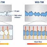
Mounting quality often changes the result more than people expect. ON Semiconductor’s mounting guide shows that contact pressure, flatness, torque, and thermal interface resistance can shift case-to-sink performance enough to change heat sink selection. In practice, that means a sink that looks adequate on paper may miss the thermal budget once grease thickness, pad compression, or uneven hardware are included. Ecothermgroup and other manufacturers usually stress the same point: validate the assembly, not just the bare sink.
| Factor | Effect on calculation | Practical note |
|---|---|---|
| Thermal interface resistance | Raises case-to-sink thermal resistance | Use realistic pad or grease values, not ideal contact numbers |
| Airflow and orientation | Changes sink-to-ambient thermal resistance | Vertical fins in open air usually perform better than a blocked horizontal mount |
| Package limits | Sets the ceiling for the thermal budget | Check package ratings before final heat sink sizing |
Mounting and Contact
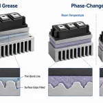
Mounting errors are common because the calculated degrees Celsius per watt often assumes a clean, uniform interface. In real builds, screws, clips, and board flex change pressure across the base, and that can raise case-to-sink thermal resistance. A practical check is to compare the designed interface with the supplier’s test condition; if the thermal interface material is different, the result is no longer a like-for-like estimate.
Use a short checklist during heat sink sizing: verify flatness, confirm clamp force, and keep the interface layer thin enough to avoid a hidden thermal penalty. For power electronics with tight limits, this step can matter as much as the heat sink selection itself.
Airflow and Orientation
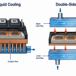
Forced-air cooling can reduce sink-to-ambient thermal resistance sharply, but the real benefit depends on fan speed, ducting, and enclosure venting. A free-air datasheet value is a starting point, not a promise. In many systems, a small airflow change moves the design from marginal to acceptable, which is why required heat sink thermal resistance must be checked in the final mechanical layout.
- Open vertical fins usually support natural convection better.
- Blocked intakes or sidewalls can reduce effective cooling.
- Multiple hot parts nearby increase the local ambient air temperature.
Package Limits
Package limits close the loop on the thermal resistance formula. If junction-to-case thermal resistance is already high, the sink must be much better to stay within the maximum junction temperature. When several devices share one sink, size it for the combined power dissipation in the real operating mode, not one device at a time. That is the common best practice for reliable thermal budget planning and is the safer way to avoid under-sizing.
For procurement and field service, this also improves comparison between candidate sinks, because it aligns the calculation with actual load, airflow, and enclosure temperature. That is the point of how to calculate heat sink thermal resistance in real hardware: the math should match the assembly that will ship, not an ideal bench setup.
Selection Workflow
To understand how to calculate heat sink thermal resistance, start with the thermal budget rather than the catalog. The usual workflow is to define the maximum junction temperature, subtract the expected ambient air temperature, and divide the remaining allowable temperature rise by the device power dissipation. For power electronics, this first-pass heat sink thermal resistance formula gives the required sink-to-ambient thermal resistance, but only after you include junction-to-case thermal resistance and case-to-sink thermal resistance in the complete thermal resistance network. In practical work, Ecothermgroup-style selection is never based on one number alone. It considers the entire path from the silicon junction to the surrounding air.
For example, if a device dissipates 25 W and can rise only 50 degrees Celsius above ambient, the total junction-to-ambient limit is 2.0 degrees Celsius per watt. If the junction-to-case resistance is 0.6 C/W and the interface adds 0.2 C/W, the heat sink itself must provide less than 1.2 C/W. That is the required heat sink thermal resistance before adding a design margin. This is why designers compare the calculated value with real heat sink data rather than relying only on the theoretical limit.
| Selection item | What to check |
|---|---|
| Thermal budget | Maximum junction temperature and ambient air temperature |
| Device path | Junction-to-case thermal resistance and case-to-sink thermal resistance |
| Heat sink target | Sink-to-ambient thermal resistance under the actual cooling method |
| Installation limits | Size, fin spacing, mounting method, and airflow direction |
Choose a Heat Sink
Heat sink sizing should reflect the actual operating conditions, not just the headline power dissipation. DigiKey’s selection approach is useful here: first estimate the allowable temperature rise, then compare it with heat sink performance under natural or forced-air cooling. ON Semiconductor’s mounting guidance adds another practical consideration: contact pressure, surface flatness, and thermal interface resistance can change the actual case-to-sink result enough to push the design beyond its limits.
In practice, engineers often choose a part with extra headroom because catalog values are generally measured under controlled conditions. A heat sink rated for the required sink-to-ambient thermal resistance in free air may perform poorly inside an enclosure or when the fins are incorrectly oriented. Forced-air cooling can allow a smaller heat sink, but only when airflow remains stable and fan operation is reliable throughout the expected duty cycle.
- Match the target C/W value to the actual mounting condition.
- Add margin for aging, dust buildup, and changes in airflow.
- Confirm that the physical package fits the board, chassis, and required service space.
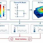
Validate the Design
The final step is to calculate junction temperature across the full operating profile. All About Circuits’ calculator approach is useful because it checks the same core variables in a straightforward way: ambient temperature, power, junction-to-package resistance, and heat sink resistance. That works well for steady-state sizing, but the analysis should also account for duty cycle and peak load. Average power can conceal short thermal spikes, which are a common source of error in first-pass heat sink selection.
Validation should include the actual thermal interface material, the expected mounting torque, and the worst-case ambient air temperature. Texas Instruments notes that package thermal metrics can be misunderstood, so engineers should use the correct junction-to-case value for the specific package rather than a generic figure. The design is ready only when the measured case temperature and modeled junction temperature both remain below the maximum junction temperature with sufficient margin.
A practical rule is simple: if the prototype operates close to the limit, do not assume the calculation is wrong. First, question whether the operating assumptions were too ideal. Recheck airflow, interface quality, mounting pressure, and enclosure effects before approving the final heat sink thermal resistance.
People Also Ask
How do I calculate the required heat sink thermal resistance from ambient temperature and power dissipation?
Start with the maximum allowed junction temperature, subtract the ambient temperature, and divide the allowable temperature rise by the power dissipation to get the total thermal resistance budget. Then subtract the device’s junction-to-case and case-to-sink resistances to find the maximum heat sink thermal resistance you can use.
Why do junction-to-case and case-to-sink resistances matter in heat sink sizing?
They are part of the full thermal path, so ignoring them usually makes the heat sink look better than it really is. In practice, the heat sink resistance can only use the portion of the thermal budget left after those package and interface resistances are included.
What real-world factors can make a calculated heat sink resistance inaccurate?
Mounting pressure, thermal interface material quality, airflow, orientation, and nearby hot components can all change the actual thermal performance. Calculations are useful for first-pass sizing, but the installed result often differs from the ideal model.
How reliable is junction-to-case thermal resistance for modern power packages?
It can be misleading if it is treated as a simple universal metric, because some package data does not represent a straightforward heat-flow path. It is better to use the manufacturer’s thermal model and application guidance when calculating heat sink resistance.
What data do I need before I can calculate heat sink thermal resistance?
You need the maximum junction temperature, expected ambient temperature, power dissipation, and the device’s thermal resistances from junction to case and case to sink. Without those inputs, you can only estimate rather than calculate the required heat sink value with confidence.
Can I use a heat sink calculator instead of doing the math myself?
Yes, a calculator is a good way to quickly estimate junction temperature, maximum power, or the required heat sink resistance. The result is only as good as the input values, so it still depends on accurate thermal data and realistic operating conditions.
Should the heat sink thermal resistance target be lower than the calculated maximum value?
Usually yes, because the calculation gives a limit, not a comfort margin. Choosing a heat sink with lower resistance provides extra headroom for manufacturing variation, warmer ambient conditions, and reduced airflow.
How do I choose a heat sink after I calculate the required thermal resistance?
Compare the calculated maximum resistance to vendor ratings under similar airflow and mounting conditions, then select a part with margin. After that, verify the full thermal stack-up, including the interface material and installation method, before finalizing the design.