IGBT Module Thermal Design: From Package Materials to Cooling Architecture
IGBT module thermal design is the process of controlling how heat moves from the semiconductor junction through the package and into air or coolant. A successful design keeps every IGBT and diode within an appropriate junction-temperature margin during both continuous and transient operation. It must also limit temperature differences across the module, survive repeated thermal expansion, fit the available space and remain consistent in production.
The cooler cannot be designed in isolation. Conduction and switching losses begin inside individual semiconductor dies, then pass through several bonded layers before reaching the heat sink or cold plate. The thermal path may include silicon, die attach, copper metallization, a ceramic substrate, substrate attach, a baseplate, thermal interface material and the external cooling component. Every layer adds thermal resistance, while material mismatch and assembly variation influence long-term reliability.
For that reason, good thermal design starts with the real operating profile rather than with a generic heat-sink catalogue value. Engineers need to know where the losses occur, how long each load condition lasts, what cooling boundary is available and how much temperature margin the application requires. Only then can the package materials, interface and cooling architecture be designed as one system.
Start with the Loss Profile, Not the Heat Sink
An IGBT module produces heat primarily through IGBT conduction loss, IGBT switching loss, diode conduction loss and diode recovery loss. These components do not remain constant. They change with current, DC-link voltage, switching frequency, modulation strategy, gate resistance, power factor and junction temperature. The highest electrical power is not always the condition that creates the highest semiconductor temperature.
A traction inverter, for example, may experience short high-current events during acceleration followed by lower continuous load. An industrial drive may operate for long periods near a stable torque. A renewable-energy inverter can follow a slowly changing daily load while being exposed to a high enclosure temperature. The thermal design must represent the actual duty cycle because the package responds differently to a short pulse and to sustained dissipation.
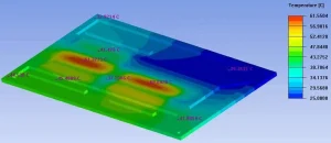
The loss calculation should separate IGBT and diode heat whenever possible. Applying the total module loss uniformly over the baseplate can hide a local hot spot, especially when one die group switches more frequently or carries more current than another. A die-level or switch-position heat map gives the mechanical designer a more realistic basis for heat spreading, channel placement and temperature measurement.
Temperature and loss also interact. Semiconductor voltage drop and switching energy vary with junction temperature, so an estimate made only at room temperature may understate or overstate the final dissipation. Near the design limit, the electrical and thermal calculations should be iterated until the loss and temperature estimates are mutually consistent.
Define the Thermal Budget and Reference Temperatures
The thermal budget divides the allowable temperature rise among the internal package, module-to-cooler interface and external cooling system. Under steady conditions, the basic relationship can be expressed as Tj = Tref + Ploss × Rth,j-ref. Tj is the junction temperature, Tref is the temperature at a clearly defined reference point, Ploss is semiconductor loss and Rth,j-ref is the thermal resistance between them.
The reference point must be unambiguous. For an air-cooled assembly it may be ambient air or a defined heat-sink location. For a liquid-cooled assembly it may be coolant inlet temperature, average coolant temperature or a cold-plate surface temperature. These are not interchangeable. Coolant warms as it passes through a channel, while a heat-sink surface can vary considerably beneath a multi-chip module.
A design should not use the absolute maximum junction temperature as its normal operating target. Loss tolerance, coolant or ambient variation, sensor error, interface variation, fouling and material aging all consume margin. The appropriate margin depends on the device qualification, service-life target and consequence of an overtemperature event, but it should be decided explicitly rather than left to chance.
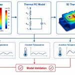
Transient conditions require more than a steady resistance. During a short power pulse, heat remains concentrated near the die and die-attach layer. With longer heating, it spreads through the substrate, baseplate and cooler. The thermal mass of these layers delays the temperature response. The module’s transient thermal impedance or a validated RC model should therefore be used for overloads, pulsed power and repeated load cycles.
Understand the IGBT Package Heat Path
In a conventional IGBT power module, the semiconductor dies are attached to a copper-metallized ceramic substrate. The upper copper layer carries current and spreads heat laterally, while the ceramic provides electrical insulation between the high-voltage circuit and the grounded or system-referenced cooling structure. The lower copper layer distributes heat into the substrate-attach layer and baseplate.
For an ideal uniform layer, thermal resistance is related to thickness, thermal conductivity and effective heat-flow area. Thinner and more conductive layers generally offer lower resistance, but the real heat path is three-dimensional. A small die transfers heat into a larger substrate and baseplate, creating spreading resistance. Adjacent IGBTs and diodes also exchange heat through the common package.
Joining layers often deserve more attention than their thickness suggests. Solder or sintered material may contain voids, thickness variation or local areas of weak contact. A void located beneath a high-loss die can raise its temperature even if the total void percentage appears acceptable. Inspection criteria should therefore consider void position and distribution, not only an average value for the complete joint.
Baseplates improve heat spreading and provide a robust mounting surface, but they add material, mass and another bonded interface. Baseplate-less modules can shorten the thermal path and reduce weight, yet they place greater demands on substrate flatness, cooler flatness and mounting-pressure control. Neither construction is automatically superior; the surrounding mechanical and cooling design determines whether the theoretical advantage can be realized.
Selecting Ceramic Substrates and Metallization
The insulated substrate performs electrical, thermal and structural functions at the same time. Alumina, aluminium nitride and silicon nitride are widely considered for power-module substrates, but their properties lead to different trade-offs. Alumina is established and economical for many applications. Aluminium nitride provides higher thermal conductivity, while silicon nitride can offer strong mechanical performance for severe thermal cycling. Thickness, copper coverage, substrate dimensions and joining method can be as important as the ceramic family itself.
Direct-bonded copper and active-metal-brazed substrates use different joining processes between the ceramic and copper. The preferred structure depends on ceramic material, copper thickness, insulation requirement, mechanical loading and manufacturing capability. Heavy copper can spread heat and carry current effectively, but it can also increase thermomechanical stress around patterned edges as the assembly heats and cools.
Electrical isolation must be evaluated under the actual operating environment. Ceramic thickness and material quality affect dielectric strength, but so do surface contamination, creepage paths, partial-discharge requirements and process defects. Reducing ceramic thickness solely to improve thermal resistance may reduce electrical or mechanical margin. The correct substrate is the one that satisfies thermal, electrical and reliability requirements together.
Selecting Ceramic Substrates and Metallization
The insulated substrate performs electrical, thermal and structural functions at the same time. Alumina, aluminium nitride and silicon nitride are widely considered for power-module substrates, but their properties lead to different trade-offs. Alumina is established and economical for many applications. Aluminium nitride provides higher thermal conductivity, while silicon nitride can offer strong mechanical performance for severe thermal cycling. Thickness, copper coverage, substrate dimensions and joining method can be as important as the ceramic family itself.
Direct-bonded copper and active-metal-brazed substrates use different joining processes between the ceramic and copper. The preferred structure depends on ceramic material, copper thickness, insulation requirement, mechanical loading and manufacturing capability. Heavy copper can spread heat and carry current effectively, but it can also increase thermomechanical stress around patterned edges as the assembly heats and cools.
Electrical isolation must be evaluated under the actual operating environment. Ceramic thickness and material quality affect dielectric strength, but so do surface contamination, creepage paths, partial-discharge requirements and process defects. Reducing ceramic thickness solely to improve thermal resistance may reduce electrical or mechanical margin. The correct substrate is the one that satisfies thermal, electrical and reliability requirements together.
Die Attach, Substrate Attach and Interconnect Materials
The die-attach layer connects the semiconductor to the substrate and sees high local heat flux. Conventional solder systems remain practical in many modules, while silver-sintered and other advanced attach processes can support higher operating temperatures and improve thermal performance. The potential benefit depends on density, bond-line uniformity, surface preparation and process control. A material name alone does not guarantee a low-resistance or durable joint.
The substrate-to-baseplate joint covers a larger area and experiences significant strain from differences in thermal expansion. Its thickness and compliance influence both heat transfer and stress. A very stiff, thin connection can reduce initial thermal resistance but transfer more strain into the ceramic or joint edges. A more compliant layer may reduce stress at the cost of additional thermal resistance. This is a coupled thermal-mechanical design decision.
Traditional aluminium or copper wire bonds create the electrical connection to the die surface. Their heel regions and bond interfaces can be sensitive to repeated junction-temperature swings. Planar interconnects, clips and ribbon bonds can change current density, parasitic inductance and heat spreading, but they also introduce their own material and process requirements. Package technology should be selected around the intended electrical load and cycling profile, not only the lowest initial temperature.
Encapsulation and housing materials affect more than mechanical protection. They influence moisture resistance, electrical insulation, wire support and stress distribution. The package must tolerate vibration, contamination and temperature variation without imposing excessive force on internal interconnects. In demanding environments, thermal design and environmental protection cannot be separated.
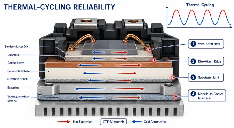
Thermal Cycling and Coefficient-of-Expansion Mismatch
Silicon, copper, ceramic, solder, sintered metal and aluminium-based cooler materials expand by different amounts as temperature changes. These differences create shear and peel stress at bonded interfaces. The effect repeats each time the power stage heats and cools, which can gradually alter die attach, substrate joints, wire bonds or the module-to-cooler interface.
Absolute temperature and temperature swing play different roles. High mean temperature can accelerate material aging, while a large and frequent junction-temperature swing increases cyclic strain. A cooling system that prevents the highest temperature but allows rapid, repeated swings may still present a reliability challenge. Control strategy, switching pattern and cooling-system response can therefore influence package life as well as immediate temperature.
Thermomechanical analysis is especially valuable when changing substrate material, copper thickness, baseplate alloy or die-attach process. A modification that lowers thermal resistance may increase stiffness or expansion mismatch elsewhere. Simulation should identify stress concentration at die corners, copper-pattern edges, substrate joints and mounting features, followed by appropriate power-cycling or thermal-cycling validation.
Design the Module-to-Cooler Interface
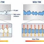
The interface between the IGBT baseplate and the cooler is one of the most production-sensitive parts of the heat path. Machined surfaces touch only at microscopic high points, while the remaining gaps contain poorly conducting air. A thermal interface material fills those gaps and creates a more continuous path into the heat sink or cold plate.
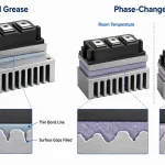
The interface material should form the thinnest complete bond line that accommodates the actual surface roughness and flatness. Applying a thick layer does not improve cooling simply because more material is present. Most interface compounds conduct heat less effectively than aluminium or copper, so excess thickness increases resistance. Too little material, however, can leave dry areas and trapped air.
Mounting pressure determines how the material wets the surfaces and how evenly the baseplate contacts the cooler. Screw location, tightening sequence, specified torque and cold-plate stiffness all influence pressure distribution. Over-tightening can distort the module or cooler, while insufficient torque raises contact resistance. The assembly process should follow the module manufacturer’s mechanical requirements and be validated on the actual cooler design.
Thermal grease can produce a thin interface when dispensing and spreading are controlled. Phase-change materials can simplify handling and improve application consistency, but they need a suitable activation temperature and mounting pressure. Pads may provide electrical insulation or tolerance accommodation where required, although their greater thickness can increase thermal resistance. Material selection should be based on measured assembly performance and aging behavior rather than conductivity alone.
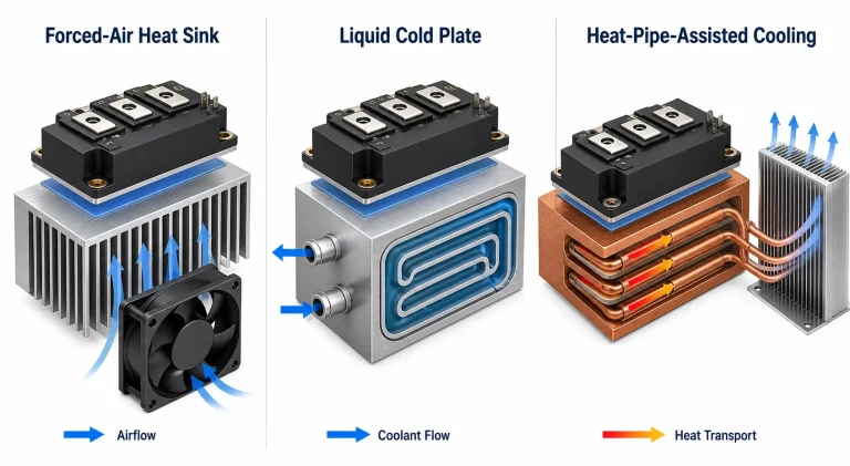
Forced-Air Heat-Sink Design
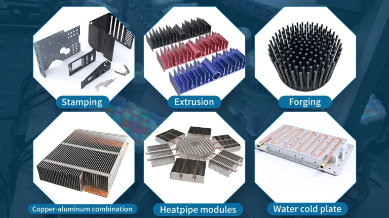
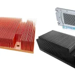
Forced-air cooling is often appropriate when loss density is moderate, the enclosure can supply enough airflow and the application values simplicity. The heat sink must spread heat from the module footprint into the fin field, then transfer it to moving air. Base thickness, fin height, fin spacing, material and airflow direction all contribute to the result.
Adding fins indefinitely does not guarantee better performance. Closely spaced fins increase surface area but can restrict airflow and raise pressure drop. A fan operates at the intersection of its pressure-flow curve and the resistance of the complete air path. Filters, grilles, cables, neighboring components and enclosure recirculation can reduce the flow that actually passes through the heat sink.
Fin orientation should support the intended flow and allow heated air to leave the enclosure without returning to the inlet. Bypass gaps around the heat sink should be controlled so air cannot take an easier path that avoids the fins. Temperature-sensitive capacitors and gate-drive electronics should not be placed in the hottest exhaust stream without considering their own limits.
Dust accumulation, altitude, fan aging and acoustic limits affect field performance. A design tested with a clean heat sink and unrestricted laboratory fan may not represent years of service. Where cooling is safety- or availability-critical, fan monitoring, redundancy or derating may be needed. Natural convection is possible at lower loss, but it requires careful orientation and generally a larger thermal surface.
Liquid Cold-Plate Design
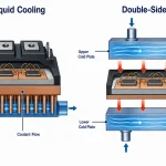
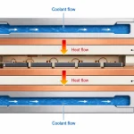
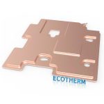
Liquid cooling is normally selected when heat flux is high, space is restricted or the application needs closer temperature control. A cold plate places flowing coolant near the module footprint, providing much higher heat capacity than air. The design challenge is to distribute that cooling uniformly while keeping pressure drop, leakage risk and pumping power within acceptable limits.
Channel geometry should follow the heat-source map. A simple passage may be sufficient for a uniform load, while parallel channels, serpentine paths, pin fins or local turbulence features can improve heat transfer beneath concentrated dies. More aggressive geometry also increases pressure drop and may become sensitive to particles or manufacturing tolerances. Thermal performance and hydraulic performance must be optimized together.
Coolant inlet temperature, flow rate and property variation define the operating boundary. The liquid warms along the flow path, so modules near the outlet may see a higher fluid temperature than those near the inlet. Parallel branches can cool several modules with a smaller temperature rise, but unequal flow distribution can create another source of imbalance. The manifold should be evaluated as part of the cold plate rather than treated as an ideal flow source.
Material compatibility is central to reliability. Aluminium, copper, stainless steel, brazing alloys, seals and fittings must be compatible with the chosen coolant and with one another. Corrosion inhibitors, electrical conductivity, freeze protection and maintenance interval should reflect the end application. Dissimilar metals and uncontrolled coolant chemistry can create galvanic or deposit-related problems that are not visible in a short thermal test.
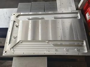
The cold plate also has structural responsibilities. Its mounting surface must remain flat under clamping load, internal pressure, brazing stress and temperature change. Connections should not transmit excessive pipe force into the module interface. Production designs require pressure testing, leak testing, cleanliness control and a repeatable method for checking flow resistance.
Heat Pipes and Vapor Chambers
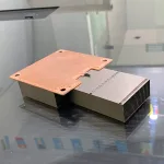
Heat pipes and vapor chambers use evaporation and condensation of a sealed working fluid to transport or spread heat. They are useful when the IGBT module cannot be located directly beside a large fin stack or when a concentrated footprint must be coupled to a wider cooling area. Their function is normally to move heat to the final air- or liquid-cooled surface, not to eliminate the need for that surface.
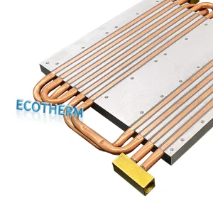
An embedded heat pipe can improve base spreading when it is positioned beneath the main heat sources and joined effectively to the surrounding metal. A vapor chamber can spread heat in two dimensions across a thin plate. The available benefit depends on operating temperature, orientation, heat input, condenser capacity, wick design and contact resistance at both ends.
Every phase-change device has transport limits. Excess heat can dry the evaporator region, overwhelm capillary return or reduce the effective condenser area. Gravity-assisted thermosyphons can move substantial heat with simple internal construction, but their operation depends on orientation. A design that performs well upright may behave differently during vehicle motion or installation at another angle.
Leak integrity and working-fluid compatibility are long-term concerns. The heat-pipe assembly should be qualified over the expected temperature, vibration and service environment. Unverified temperature reductions from another geometry should not be transferred directly to a new design because pipe diameter, fill ratio, fin arrangement and boundary conditions can change the outcome.
Choosing the Cooling Architecture
The correct architecture depends on the required heat removal and the constraints surrounding it. A forced-air heat sink is attractive when moderate loss, sufficient fin volume and reliable airflow are available. It avoids pumps, coolant and seals, but fan noise, dust and ambient temperature may limit performance. It is often the most straightforward option for stationary equipment with adequate enclosure space.
A liquid cold plate is usually more suitable for compact, high-power assemblies or systems that already contain a liquid loop. It can maintain a lower and more uniform module-base temperature, but it adds hydraulic, corrosion, sealing and service requirements. The pump and remote heat exchanger remain part of the thermal chain; a cold plate cannot reject heat indefinitely without them.
Heat-pipe-assisted cooling fits applications where heat must travel from the module to a remote or larger heat exchanger without adding a pumped liquid loop. It can also improve spreading within an air-cooled design. The solution becomes less attractive when orientation varies beyond the qualified range, when the condenser cannot reject the transported heat or when packaging leaves poor contact at the evaporator.
Selection should consider the complete life cycle. Initial thermal resistance matters, but so do production yield, assembly time, maintenance, contamination, vibration, acoustic limits, redundancy and failure detection. The best laboratory temperature does not automatically produce the best industrial product.
Control Temperature Uniformity Across the Module
Average case temperature can hide a problematic local junction. Multi-chip modules contain discrete heat sources arranged over a common substrate, and the heat does not always divide evenly. Current sharing, modulation and diode conduction can cause one position to run hotter. External cooling can add further non-uniformity through air preheating or coolant temperature rise.
Heat spreading should begin close to the dies. Copper metallization, substrate layout and baseplate thickness influence how the heat footprint expands before it reaches the cooler. Outside the module, the heat-sink base or cold-plate wall must continue that spreading without adding excessive thickness. A very thin cold-plate wall may bring coolant close to the module but provide insufficient lateral conduction between channels.
The cooling geometry should align with the actual die map rather than only with the module outline. Local channel enhancement beneath the highest-loss switch position can reduce its temperature, but excessive local cooling can also increase temperature gradients and thermomechanical strain. The goal is not merely the lowest single temperature; it is a controlled, predictable temperature field with adequate margin at every semiconductor.
Use Simulation Without Losing the Physical Design
Computational fluid dynamics and finite-element analysis help compare geometries before prototypes are built. A useful model includes realistic die or switch losses, contact resistance, material properties, coolant conditions and enclosure flow. Simplifying the module as a uniform heat source may be acceptable for an early screening study, but the limitation should be understood.
Mesh refinement is especially important around thin attach layers, channel walls and local heat sources. Boundary conditions should match how the hardware will be tested. Specifying a fixed cold-plate temperature, for example, can overstate performance if the real plate is cooled by fluid that warms and flows non-uniformly.
Simulation is most valuable for comparing design changes and identifying hot spots. It should not be treated as proof of final temperature without measurement. Contact resistance, interface thickness, material variation and flow distribution are difficult to predict perfectly. Test data should be used to calibrate uncertain parameters, followed by confirmation at operating points that were not used for calibration.
Prototype and Production Validation
Thermal validation should reproduce the combinations of loss, coolant or ambient temperature and flow that create the highest junction temperature. Case thermocouples, cold-plate sensors, coolant inlet and outlet measurements, airflow measurements and infrared inspection each reveal a different part of the heat path. Junction temperature can be estimated through a validated thermal model or a calibrated temperature-sensitive electrical parameter where the test method allows it.
An energy balance is a useful check in liquid systems. The coolant flow and temperature rise should be consistent with the heat being removed, within measurement uncertainty and allowance for heat lost elsewhere. A mismatch can reveal sensor error, bypass flow, unexpected enclosure losses or an incorrect electrical-loss estimate.
Reliability testing should examine whether the thermal path changes with time. Power cycling stresses the internal package through repeated semiconductor heating, while thermal cycling exposes the complete assembly to environmental temperature variation. Vibration, coolant aging and mechanical load can affect interfaces and seals. Repeating selected thermal measurements after these tests helps detect degradation that a visual inspection may miss.
Production controls are necessary to reproduce prototype performance. Relevant controls may include cooler flatness, surface finish, interface-material mass or thickness, tightening sequence, torque, flow resistance, cleanliness and leak integrity. A thermal design is not complete until these characteristics can be measured and maintained from one assembly to the next.
Common IGBT Thermal-Design Mistakes
A frequent mistake is choosing a cooler from total module power without examining die-level loss or the duty cycle. This can produce an acceptable average base temperature while one IGBT or diode exceeds its intended margin. Another is combining thermal-resistance values that use incompatible reference temperatures or test fixtures.
Interface performance is also often treated as a material property rather than an assembly result. High advertised conductivity cannot compensate for excessive bond-line thickness, poor flatness or uneven pressure. Similarly, a cold plate with a low simulated resistance can perform poorly if the manifold distributes flow unevenly or if brazing distortion changes the mounting surface.
Designers sometimes optimize only the new condition. Dust, fan degradation, coolant-property change, corrosion, pump variation and thermal-interface aging can all raise temperature later in service. Finally, lowering thermal resistance without checking expansion mismatch may increase stress in another package layer. The thermal, mechanical and manufacturing designs should be reviewed together.
Frequently Asked Questions
What is the most important input for IGBT module thermal design?
The most important input is a realistic loss profile separated by IGBT and diode position over the intended duty cycle. The design also needs maximum coolant or ambient temperature, junction-temperature limits, module geometry, installation space and service-life requirements. Without those inputs, cooler selection is largely an assumption.
Which ceramic substrate is best for an IGBT module?
There is no universal best material. Alumina is suitable for many established designs, aluminium nitride offers higher thermal conductivity, and silicon nitride can provide strong mechanical performance for demanding cycling. The selection must also consider copper thickness, electrical insulation, substrate dimensions, joining process, reliability and cost.
Is liquid cooling always better than air cooling for an IGBT?
Liquid cooling can remove more heat from a smaller volume and provide tighter temperature control, but it adds pumps, seals, coolant management and leak risk. Air cooling may be the better system solution when losses are moderate, sufficient space is available and simplicity or serviceability has higher priority.
How does thermal interface material affect junction temperature?
The interface material fills microscopic gaps between the module and cooler. Its effective resistance depends on conductivity, final thickness, surface flatness, pressure, voiding and aging. A thin, uniform and well-controlled interface generally performs better than an unnecessarily thick layer of a nominally conductive material.
When should a heat pipe be used for IGBT cooling?
A heat pipe is useful when heat must be transported from a compact module area to a remote fin stack or when spreading in a conventional base is insufficient. Its operating temperature, orientation, transport limit, condenser performance and contact resistance must be matched to the application.
Why can an IGBT module fail even when its maximum temperature is acceptable?
Package damage can be driven by repeated temperature swing and expansion mismatch, not only by the highest temperature. Wire bonds, die attach and substrate joints experience cyclic strain as the module heats and cools. Reliability assessment should therefore consider mean temperature, temperature swing, cycle duration and number of cycles.
What information does Ecothermgroup need for a custom IGBT cooler?
A practical review needs the IGBT module drawing, mounting surface and hole locations, loss map or operating power, duty cycle, maximum ambient or coolant temperature, available envelope and expected quantity. For liquid cooling, the coolant type, flow-rate range, allowable pressure drop, connection positions and material restrictions are also important.